
Arduino SPI Tutorial
This Arduino SPI tutorial describes how to set up and use the on-chip Serial Peripheral Interface (SPI) of the Arduino Board. Serial Peripheral Interface (SPI) is a synchronous serial data protocol used by microcontrollers for communicating with one or more peripheral devices quickly over short distances. It can also be used for communication between two microcontrollers. With an SPI connection there is always one master device (usually a microcontroller) which controls the peripheral devices. It is a full duplex connection, which means that the data is sent and received simultaneously. The maximum baud rate is higher than that in the I2C communication system.
Typically there are three lines common to all the devices:
- MISO (Master In Slave Out) – The Slave line for sending data to the master,
- MOSI (Master Out Slave In) – The Master line for sending data to the peripherals,
- SCK (Serial Clock) – The clock pulses which synchronize data transmission generated by the master
and one line specific for every device:
- SS (Slave Select) – the pin on each device that the master can use to enable and disable specific devices.
When a device’s Slave Select pin is low, it communicates with the master. When it’s high, it ignores the master. This allows you to have multiple SPI devices sharing the same MISO, MOSI, and CLK lines.
To write code for a new SPI device you need to note a few things:
- What is the maximum SPI speed your device can use? This is controlled by the first parameter in SPISettings. If you are using a chip rated at 15 MHz, use 15000000. Arduino will automatically use the best speed that is equal to or less than the number you use with SPISettings.
- Is data shifted in Most Significant Bit (MSB) or Least Significant Bit (LSB) first? This is controlled by second SPISettings parameter, either MSBFIRST or LSBFIRST. Most SPI chips use MSB first data order.
- Is the data clock idle when high or low? Are samples on the rising or falling edge of clock pulses? These modes are controlled by the third parameter in SPISettings.
The SPI standard is loose and each device implements it a little differently. This means you have to pay special attention to the device’s datasheet when writing your code.
Note about Slave Select (SS) pin on AVR based boards
All AVR based boards have an SS pin that is useful when they act as a slave controlled by an external master. Since this library supports only master mode, this pin should be set always as OUTPUT otherwise the SPI interface could be put automatically into slave mode by hardware, rendering the library inoperative.
It is, however, possible to use any pin as the Slave Select (SS) for the devices. For example, the Arduino Ethernet shield uses pin 4 to control the SPI connection to the on-board SD card, and pin 10 to control the connection to the Ethernet controller.
Connections
The following table display on which pins the SPI lines are broken out on the different Arduino boards:
| Arduino / Genuino Board | MOSI | MISO | SCK | SS (slave) | SS (master) | Level |
| Uno or Duemilanove | 11 or ICSP-4 | 12 or ICSP-1 | 13 or ICSP-3 | 10 | – | 5V |
| Mega1280 or Mega2560 | 51 or ICSP-4 | 50 or ICSP-1 | 52 or ICSP-3 | 53 | – | 5V |
| Leonardo | ICSP-4 | ICSP-1 | ICSP-3 | – | – | 5V |
| Due | ICSP-4 | ICSP-1 | ICSP-3 | – | 4, 10, 52 | 3,3V |
| Zero | ICSP-4 | ICSP-1 | ICSP-3 | – | – | 3,3V |
| 101 | 11 or ICSP-4 | 12 or ICSP-1 | 13 or ICSP-3 | 10 | 10 | 3,3V |
| MKR1000 | 8 | 10 | 9 | – | – | 3,3V |
Note that MISO, MOSI, and SCK are available in a consistent physical location on the ICSP header; this is useful, for example, in designing a shield that works on every board.
Arduino SPI Library
The interconnection between two SPI devices always happens between a master device and a slave device. The master is the active part in this system and has to provide the clock signal a serial data transmission is based on. The slave is not capable of generating the clock signal and thus can not get active on its own. The slave just sends and receives data, if the master generates the necessary clock signal. The master, however, generates the clock signal only while sending data. That means the master has to send data to the slave to read data from the slave.
The following functions are used. You have to include the SPI.h.
- SPI.begin() − Initializes the SPI bus by setting SCK, MOSI, and SS to outputs, pulling SCK and MOSI low, and SS high.
- SPI.setClockDivider(divider) − To set the SPI clock divider relative to the system clock. On AVR based boards, the dividers available are 2, 4, 8, 16, 32, 64 or 128. The default setting is SPI_CLOCK_DIV4, which sets the SPI clock to one-quarter of the frequency of the system clock (5 Mhz for the boards at 20 MHz).
- Divider − It could be (SPI_CLOCK_DIV2, SPI_CLOCK_DIV4, SPI_CLOCK_DIV8, SPI_CLOCK_DIV16, SPI_CLOCK_DIV32, SPI_CLOCK_DIV64, SPI_CLOCK_DIV128).
- SPI.transfer(val) − SPI transfer is based on a simultaneous send and receive: the received data is returned in receivedVal.
- SPI.beginTransaction(SPISettings(speedMaximum, dataOrder, dataMode)) − speedMaximum is the clock, dataOrder(MSBFIRST or LSBFIRST), dataMode(SPI_MODE0, SPI_MODE1, SPI_MODE2, or SPI_MODE3).
Generally speaking, there are four modes of transmission. These modes control whether data is shifted in and out on the rising or falling edge of the data clock signal (called the clock phase), and whether the clock is idle when high or low (called the clock polarity). The four modes combine polarity and phase according to this table:
| Mode | Clock Polarity (CPOL) | Clock Phase (CPHA) | Output Edge | Data Capture |
| SPI_MODE0 | 0 | 0 | Falling | Rising |
| SPI_MODE1 | 0 | 1 | Rising | Falling |
| SPI_MODE2 | 1 | 0 | Rising | Falling |
| SPI_MODE3 | 1 | 1 | Falling | Rising |
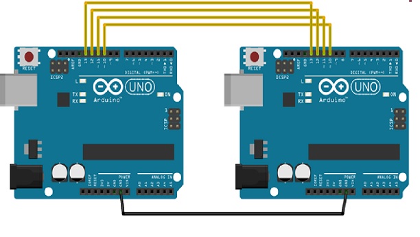
Now, we will connect two Arduino UNO boards together; one as a master and the other as a slave.
- (SS) : pin 10
- (MOSI) : pin 11
- (MISO) : pin 12
- (SCK) : pin 13
The ground is common. Following is the diagrammatic representation of the connection between both the boards −
Examples
Arduino SPI as Master
Master unit sends hello world data to slave unit.
#include <SPI.h>

void setup (void) {
Serial.begin(115200); //set baud rate to 115200 for usart
digitalWrite(SS, HIGH); // disable Slave Select
SPI.begin ();
SPI.setClockDivider(SPI_CLOCK_DIV8);//divide the clock by 8
}

void loop (void) {
char c;
digitalWrite(SS, LOW); // enable Slave Select
// send test string
for (const char * p = "Hello, world!\r" ; c = *p; p++)
{
SPI.transfer (c);
Serial.print(c);
}
digitalWrite(SS, HIGH); // disable Slave Select
delay(2000);
}
Arduino SPI as Slave
Slave unit waits for data as soon as data is arrived process variable becomes true, indicating there is data in buffer. in main loop we read this buffer and send to serial terminal.
#include <SPI.h>
char buff [50];
volatile byte indx;
volatile boolean process;

void setup (void) {
Serial.begin (115200);
pinMode(MISO, OUTPUT); // have to send on master in so it set as output
SPCR |= _BV(SPE); // turn on SPI in slave mode
indx = 0; // buffer empty
process = false;
SPI.attachInterrupt(); // turn on interrupt
}

ISR (SPI_STC_vect) // SPI interrupt routine
{
byte c = SPDR; // read byte from SPI Data Register
if (indx < sizeof buff) {
buff [indx++] = c; // save data in the next index in the array buff
if (c == '\r') //check for the end of the word
process = true;
}
}

void loop (void) {
if (process) {
process = false; //reset the process
Serial.println (buff); //print the array on serial monitor
indx= 0; //reset button to zero
}
}
Open serial monitor of slave, you will see “Hello, World”.
I hope you like this post. Do you have any questions? Leave a comment down below! Thanks for reading. If you like this post probably you might like my next ones, so please support me by subscribing my blog.
You may also like:
- Dynamic WLAN configuration for ESP32 Board | AutoConnect
- ESP32 BLE on Arduino IDE with UART Test
- ESP32 Bluetooth Low Energy (BLE) on Arduino IDE
- ArduinoOTA ESP32: Wi-Fi (OTA) Wireless Update from the Arduino IDE
- ESP32 with LoRa using Arduino IDE
- How To Use Grove-LCD RGB Backlight with NodeMCU
- NodeMcu to DHT Interface in Blynk app
- How To ON/OFF a bulb by Google voice assistant
- Arduino IDE | Arduino | Open Source Hardware/Softawre | Arduino Vs RPi
- WiFi LoRA 32 (V2) ESP32 | Overview | Introduction
- DHT11 sensor with ESP8266/NodeMCU using Arduino IDE
- Arduino Support for ESP8266 with simple test code
Explore Some more Raspberry Pi Tutorials :
- Raspberry Pi – Introduction | Overview | Setup and Management | Tutorials
- How to Install Mosquitto Broker on Raspberry Pi
- Setting up SPI on Raspberry Pi
- Getting Started with The Sense HAT – Raspberry Pi
- Raspberry Pi GPIO Basics
- Controlling LED with Raspberry Pi PART-2
- How To Setup Static IP Address on Raspberry Pi
- Controlling LED with Raspberry Pi
- Interfacing a light Sensor (LDR) with Raspberry Pi
- Remote control your Raspberry Pi from your PC with VNC!
- How To Use Raspberry pi in a truely headless mode
- ROCK Pi 4 : Overview | Installation
- Best OS for Raspberry Pi
- How to setup Bluetooth on a Raspberry Pi 3
- Simple Raspberry Pi Home Security System
- Raspbian – OS For Raspberry Pi
- Setting up a Raspberry Pi headless
Buy now : Raspberry PI 3 Model B+ Motherboard

Pingback: ESP8266 Tutorials | NodeMCU Programming | Arduino IDE
Pingback: Arduino SPI Tutorial - CompileIoT - CompileIoT - Expolre Internet of Things