LED using Blynk and ESP8266 (Node MCU)
Here, in this project we are controlling a LED using Blynk and Esp8266. Blynk was designed for the Internet of Things. It is most popular IoT Platform. It can control hardware remotely, it can display sensor data, it can store data, vizualize it and do many other cool things. With Blynk Library you can connect over 400 hardware models (including ESP8266, ESP32, NodeMCU, all Arduinos, Raspberry Pi, Particle, Texas Instruments, etc.)to the Blynk Cloud. Full list of supported hardware can be found here.
For more information about Blynk :
Visit this : Blynk IoT Platform
Visit this Post : NodeMcu to DHT Interface in Blynk app
Components Required
- BYNK APP (Download from Play Store)
- ESP8266 NODEMCU
Blynk App Dashboard Setup for Controlling LED
To control LED with Blynk app, download and install the Blynk app from Google or Apple app store.
After sign up click on ‘New Project’ to start your project. Now provide your project a name and as blynk app works with diffferent hardware models.
Thus opt for your device from choices. Here, we are using ESP8266 nodeMCU.
While selecting your board opt for your association sort whether or not it’s Wi-Fi or LAN or USB association.
After these steps click on ‘Create’ button to form your project.
As, the blank project opens, add Widgets to it by clicking on Add button (Plus sign button)
Now after this click on ‘Button’ to add a button in your project.
Now in button settings provide a name to your button. After assign the pin number to the ‘OUTPUT’. Also, give names to your On/Off labels.
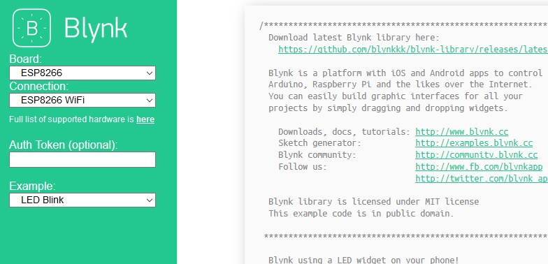
NODE MCU Setup for Blynk App
Open this link your browser https://examples.blynk.cc/ . Select your board “ESP8266” and example code “LED Blink”.
Now open Arduino IDE and setup environment for ESP8266 NodeMCU Board. If you are not familiar with Arduino IDE.
Visit This : Arduino Support for ESP8266 with simple test code
Now copy the example code from the browser as mentioned above and paste in Arduino IDE.
Arduino Sketch code Explanation
The complete code for Controlling LED using Blynk App and ESP8266 is given at the end. Includeall the required libraries for ESP8266 and Blynk App in the code, as shown below:
#define BLYNK_PRINT Serial
#include <ESP8266WiFi.h>
#include <BlynkSimpleEsp8266.h>
Enter the Auth Token in the code, which you can get from the Blynk App or from the mail you have received from Blynk.
char auth[ ] = "YourAuthToken";
To connect with WIFI enter your SSID name and password
char ssid[ ] = "YourNetworkName";
char pass[ ] = "YourPassword";
Here, void blinkLedWidget() function is used for switching ON and OFF the LED.
void blinkLedWidget()
{
  if (led1.getValue()) {
    led1.off();
    Serial.println("LED on V1: off");
  } else {
    led1.on();
    Serial.println("LED on V1: on");
  }
}
In void setup( ) function, we will initialize the baud rate, LED output and will connect the module with the Wi-Fi using Blynk.begin(auth,ssid,password); function. This function begins the Wi-Fi connection.
void setup()
{
  Serial.begin(9600);
  Blynk.begin(auth, ssid, pass);
  timer.setInterval(1000L, blinkLedWidget);
}
Testing LED Control using Blynk App and ESP
Now, copy and paste the complete code into Arduino IDE. Then upload the code into the ESP8266. Then, open the Blynk App for controlling the LED from the button widget.
Complete Code
#define BLYNK_PRINT Serial
#include <ESP8266WiFi.h>
#include <BlynkSimpleEsp8266.h>

// You should get Auth Token in the Blynk App.
// Go to the Project Settings (nut icon).

char auth[ ] = "YourAuthToken";

// Your WiFi credentials.
// Set password to "" for open networks.

char ssid[ ] = "YourNetworkName";
char pass[ ] = "YourPassword";

WidgetLED led1(V1);
BlynkTimer timer;

// V1 LED Widget is blinking
void blinkLedWidget()  // function for switching off and on LED
{
  if (led1.getValue()) {
    led1.off();
    Serial.println("LED on V1: off");
  } else {
    led1.on();
    Serial.println("LED on V1: on");
  }
}

void setup()
{
  Serial.begin(9600);
  Blynk.begin(auth, ssid, pass);
  timer.setInterval(1000L, blinkLedWidget);
}

//In the loop function include Blynk.run() command.
void loop()
{
  Blynk.run();
  timer.run();
}
I hope you like this post. Do you have any questions? Leave a comment down below!
Thanks for reading. If you like this post probably you might like my next ones, so please support me by subscribing my blog.
We have other tutorials with ESP32 that you may find useful:
- Dynamic WLAN configuration for ESP32 Board | AutoConnect
- ArduinoOTA ESP32: Wi-Fi (OTA) Wireless Update from the Arduino IDE
- ESP32 with LoRa using Arduino IDE
- How To Use Grove-LCD RGB Backlight with NodeMCU
- How To ON/OFF a bulb by Google voice assistant
- Arduino IDE | Arduino | Open Source Hardware/Softawre | Arduino Vs RPi
- WiFi LoRA 32 (V2) ESP32 | Overview | Introduction
- DHT11 sensor with ESP8266/NodeMCU using Arduino IDE
- Arduino Support for ESP8266 with simple test code
You may like also:
- Raspberry Pi – Introduction | Overview | Setup and Management | Tutorials
- MQTT | What is MQTT | MQTT in Depth | QoS | FAQs | MQTT Introduction
- How to set up Windows 10 IoT Core on the Raspberry Pi
- Best IoT Visual Programming Tools