
Integrating 28BYJ-48 Stepper Motor and ULN2003 Motor Driver with ESP8266 NodeMCU: A Practical Approach
In this tutorial, discover the process of managing a stepper motor through the ESP8266 NodeMCU board. We’ll be working with the 28BYJ-48 unipolar stepper motor and the ULN2003 motor driver, and programming the ESP8266 board through the Arduino IDE.
Components Required
To successfully engage in this tutorial, it’s essential to gather the following components. With these components in hand, you’ll have everything you need to dive into this tutorial, exploring the details of controlling a stepper motor using the ESP8266 NodeMCU board. This setup will enable you to gain valuable insights into the complex facts of stepper motor operation and control.
- 28BYJ-48 Stepper Motor: This unipolar stepper motor serves as a essential element in our setup, contributing to precise control and motion.
- ULN2003 Motor Driver: The ULN2003 motor driver is integral for efficiently managing the stepper motor, ensuring smooth and controlled movements.
- ESP8266 (Consider consulting our guide on Best ESP8266 Development Boards): The ESP8266 NodeMCU board acts as the central control unit, managing the operation and communication with the stepper motor.
- Jumper Wires: These wires are the channels facilitating electrical connections between various components, promoting a seamless and organized setup.
- 5V Power Supply: A stable power source is crucial for the reliable performance of the stepper motor system, and a 5V power supply fulfills this requirement.
What is a Stepper Motor?
A stepper motor is a type of electric motor that is widely used in various industries and applications. It is designed to convert electrical pulses into precise mechanical movements, making it ideal for applications that require accurate positioning and control. Unlike traditional motors that rotate continuously, a stepper motor moves in small, discrete steps or increments. Each step is a fixed angle, typically 1.8 degrees or 0.9 degrees, depending on the motor’s design. The number of steps per revolution determines the motor’s resolution and precision.
Stepper motors consist of several key components, including a rotor, stator, and coils. The rotor is the rotating part of the motor, while the stator houses the coils and magnets. The coils are energized in a specific sequence, causing the rotor to move in a step-by-step manner. One of the main advantages of stepper motors is their ability to maintain precise positioning without the need for feedback sensors. This makes them highly reliable and suitable for applications where accuracy is crucial, such as CNC machines, 3D printers, robotic arms, and automated manufacturing systems.
28BYJ-48 Stepper Motor
Multiple stepper motors with varying specifications exist. This guide focuses on the widely utilized 28BYJ-48 unipolar stepper motor, paired with the ULN2003 motor driver. Here are some Key Characteristics of the 28BYJ-48 Stepper Motor:
- Rated Voltage: 5V DC
- Number of Phases: 4
- Speed Variation Ratio: 1/64
- Stride Angle: 5.625º/64
- Frequency: 100Hz
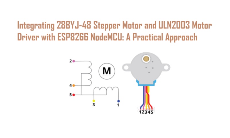
The 28BYJ-48 motor comprises four coils. One coil end connects to 5V (corresponding to the red wire), while the other coil end relates to the wires colored blue, pink, yellow, and orange. Consecutively activating the coils prompts the motor to move one step in either direction.

In half-step mode, the 28BYJ-48 Stepper Motor has a stride angle of 5.625°/64, meaning it requires 64 steps for a complete rotation. For full-step mode, it takes 32 steps to complete one rotation. Nevertheless, due to a 64:1 gear ratio driving the output shaft, the motor must perform 2048 steps for the visible shaft to complete a full rotation. Consequently, this results in a precision of 0.18º/step (360º/2048 steps). To sum up: The complete revolution consists of 2048 individual steps, and each step corresponds to an angle of 0.18 degrees.
ULN2003 Motor Driver
To connect the stepper motor to the ESP8266 NodeMCU board, we’ll employ the ULN2003 motor driver, depicted in the illustration provided. It’s common for the 28BYJ-48 stepper motor to be bundled with the ULN2003 motor driver in many instances.

There are designated pins for linking VCC and GND, accompanied by a jumper cap functioning as an ON/OFF switch for supplying power to the stepper motor. By removing the jumper, you cut off the power supply to the motor. These pins can be utilized for connecting a physical switch.
The following table shows the module pinout:
| IN1 | Control the motor: connect to a microcontroller digital pin |
| IN2 | Control the motor: connect to a microcontroller digital pin |
| IN3 | Control the motor: connect to a microcontroller digital pin |
| IN4 | Control the motor: connect to a microcontroller digital pin |
| VCC | Powers the motor |
| GND | Common GND |
| Motor connector | Connect the motor connector |
How to wire the stepper motor to the ESP8266 board
In this segment, we will establish a connection between the ESP8266 and the stepper motor using the ULN2003 motor driver. Link IN1, IN2, IN3, and IN4 to GPIOs 5, 4, 14, and 12, respectively. Alternatively, choose other appropriate digital pins (refer to our ESP8266 pinout reference guide).

| Motor Driver | ESP8266 |
| IN1 | GPIO 5 |
| IN2 | GPIO 4 |
| IN3 | GPIO 14 |
| IN4 | GPIO 12 |
Installing the AccelStepper Library
There are various methods to manage stepper motors with a microcontroller. In the case of the ESP8266 and stepper motor, we will employ the AccelStepper library. This library simplifies the process of moving the motor by a defined number of steps, adjusting its speed, acceleration, and more. For detailed guidance on utilizing its methods, the library offers comprehensive documentation, accessible here.
Follow these steps to integrate the library into your Arduino IDE:
- Navigate to Sketch > Include Library > Manage Libraries…
- Search for “accelstepper.”
- Install the AccelStepper library developed by Mike McCauley. We recommend version 1.61.0.

Control Stepper Motor with the ESP8266 – Code
Paste the code provided below into your Arduino IDE. In this illustration, the motor will continuously execute one clockwise rotation followed by a counterclockwise rotation.
/* Complete project details at https://iotbyhvm.ooo/Integrating 28BYJ-48 Stepper Motor and ULN2003 Motor Driver with ESP8266 NodeMCU: A Practical Approach/
*/

#include <AccelStepper.h>
const int stepsPerRevolution = 2048; // change this to fit the number of steps per revolution//

// ULN2003 Motor Driver Pins
#define IN1 5
#define IN2 4
#define IN3 14
#define IN4 12

// initialize the stepper library
AccelStepper stepper(AccelStepper::HALF4WIRE, IN1, IN3, IN2, IN4);

void setup() {
// initialize the serial port
Serial.begin(115200);
// set the speed and acceleration
stepper.setMaxSpeed(500);
stepper.setAcceleration(100);
// set target position stepper.moveTo(stepsPerRevolution);
}
void loop() {
// check current stepper motor position to invert direction
if (stepper.distanceToGo() == 0){
stepper.moveTo(-stepper.currentPosition());
Serial.println("Changing direction"); }
// move the stepper motor (one step at a time)
stepper.run();
}
Transfer the code to your board. Once uploaded, the motor will repeatedly perform one clockwise rotation followed by a counterclockwise rotation. It initiates the rotation at a lower speed and gradually accelerates to the desired speed before reaching the target position.
Conclusion
In conclusion, this tutorial demonstrated the integration and control of a 28BYJ-48 stepper motor with an ESP8266 NodeMCU board using the ULN2003 motor driver. Key components, including the motor driver and ESP8266, were connected following a clear wiring guide. The AccelStepper library facilitated precise control. The tutorial highlighted the specifications of the 28BYJ-48 motor and concluded with a concise code snippet for continuous clockwise and counterclockwise rotations. This practical guide equips users with the knowledge and tools to implement stepper motor control in various projects, especially in automation and robotics.


