
ESP32 Tutorials | ESP32 BLE | ESP32 add-on Arduino IDE | How To Use
In the post you can explore some esp32 tutorials. This is for beginners. Esp32 And ESP8266 both most popular development boards. ESP32 and ESP8266 are cheap Wi-Fi modules perfectly suited for DIY projects in the Internet of Things (IoT) field. These modules come with GPIOs, support for a variety of protocols like SPI, I2C, UART, and more. The best part is that they come with wireless networking included, which makes them apart from other micro-controllers like the Arduino. This means that you can easily control and monitor devices remotely via Wi-Fi for a very low price.
ESP32 chip specifications –
- The ESP32 is dual core, this means it has 2 processors.
- It has Wi-Fi and bluetooth built-in.
- It runs 32 bit programs.
- The clock frequency can go up to 240MHz and it has a 512 kB RAM.
- This particular board has 30 or 36 pins, 15 in each row.
- It also has wide variety of peripherals available, like: capacitive touch, ADCs, DACs, UART, SPI, I2C and much more.
- It comes with built-in hall effect sensor and built-in temperature sensor.
ESP32 vs ESP8266
Here you can see a table that adapted by AMICA IO. This table shows main differences between the ESP8266 and the ESP32 processors (table adapted from: AMICA_IO).
|
ESP8266
|
ESP32
|
|
|---|---|---|
|
MCU
|
Xtensa Single-core 32-bit L106
|
Xtensa Dual-Core 32-bit LX6 with 600 DMIPS
|
|
802.11 b/g/n Wi-Fi
|
HT20
|
HT40
|
|
Bluetooth
|
X
|
Bluetooth 4.2 and BLE
|
|
Typical Frequency
|
80 MHz
|
160 MHz
|
|
SRAM
|
X
|
✓
|
|
Flash
|
X
|
✓
|
|
GPIO
|
17
|
36
|
|
Hardware /Software PWM
|
None / 8 channels
|
None / 16 channels
|
|
SPI/I2C/I2S/UART
|
2/1/2/2
|
4/2/2/2
|
|
ADC
|
10-bit
|
12-bit
|
|
CAN
|
X
|
✓
|
|
Ethernet MAC Interface
|
X
|
✓
|
|
Touch Sensor
|
X
|
✓
|
|
Temperature Sensor
|
X
|
✓
|
|
Hall effect sensor
|
X
|
✓
|
|
Working Temperature
|
-40ºC to 125ºC
|
-40ºC to 125ºC
|
You can set PWM signals in any GPIO with configurable frequencies and duty cycles set on the code. When it comes to the analog pins, these are static, but the ESP32 supports measurements on 18 channels (analog-enabled pins) versus one 10-bit ADC pin on the ESP8266. The ESP32 also supports two 8-bit DAC channels. Additionally, the ESP32 contains 10 capacitive sensing GPIOs, that detect touch and can be used to trigger events, or wake-up the ESP32 from deep sleep, for example.
If you’re familiar with the ESP8266, the ESP32 is its sucessor. The ESP32 is loaded with lots of new features. The most relevant: it combines WiFi and Bluetooth wireless capabilities and it’s dual core. Some Boards comes with LoRa such as WiFi LoRA 32 (V2) ESP32 | Overview | Introduction.
ESP32 Pinout
The ESP32 has more GPIOs with more functionalities compared with the ESP826. With the ESP32 you can decide which pins are UART, I2C, or SPI – you just need to set that on the code. This is possible due to the ESP32 chip’s multiplexing feature that allows to assign multiple functions to the same pin. If you don’t set them on the code, the pins will be used as default
Version with 30 GPIOs
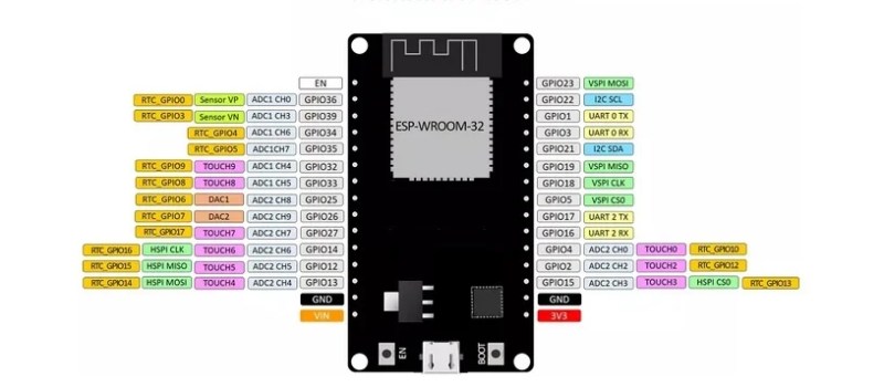
Version with 36 GPIOs

Programming Environments
The ESP32 can be programmed in different programming environments. You can use: Arduino IDE, Espressif IDF (IoT Development Framework), Micropython, JavaScript, LUA etc. We use Arduino IDE for all ESP32 Tutorials.
Arduino IDE ?
The Arduino integrated development environment (IDE) is a cross-platform application (for Windows, macOS, Linux) that is written in the programming language Java. It is used to write and upload programs to Arduino board. This IDE allows for program writing, code verfication, compiling, and uploading to the Arduino development board. Libraries and example code will also be installed. The Arduino IDE supports the languages C and C++ using special rules of code structuring. The Arduino IDE supplies a software library from the Wiring project, which provides many common input and output procedures. User-written code only requires two basic functions, for starting the sketch and the main program loop, that are compiled and linked with a program stub main() into an executable cyclic executive program with the GNU toolchain, also included with the IDE distribution. The Arduino IDE employs the program avrdude to convert the executable code into a text file in hexadecimal encoding that is loaded into the Arduino board by a loader program in the board’s firmware.
In the Arduino Software page you will find two options:
- If you have a reliable Internet connection, you should use the online IDE (Arduino Web Editor). It will allow you to save your sketches in the cloud, having them available from any device and backed up. You will always have the most up-to-date version of the IDE without the need to install updates or community generated libraries.
- If you would rather work offline, you should use the latest version of the desktop IDE.
Read more…Recommended : Best Arduino IDE alternatives to start programming
Installing the ESP32 Board in Arduino IDE for ESP32 tutorials
IMPORTANT NOTE
:
- If this is your first time installing the ESP32 on the Arduino IDE, simply follow the installation procedure described below;
- If you’ve already installed the ESP32 add-on using the old method, you should remove the espressif folder first. Go to the end of this post to learn how to remove the espressif folder.
1. Installing the ESP32 Board
To install the ESP32 board in your Arduino IDE, follow these next instructions:
1) Open the preferences window from the Arduino IDE. Go to File> Preferences
2) Enter https://dl.espressif.com/dl/package_esp32_index.json into the “Additional Board Manager URLs” field as shown in the figure below. Then, click the “OK” button:

Note: if you already have the ESP8266 boards URL, you can separate the URLs with a comma as follows:
https://dl.espressif.com/dl/package_esp32_index.json, http://arduino.esp8266.com/stable/package_esp8266com_index.json
3) Open boards manager. Go to Tools > Board > Boards Manager…

4) Search for ESP32 and press install button for the “ESP32 by Espressif Systems“:

5) That’s it. It should be installed after a few seconds.
2. Deleting the espressif folder
If this is your first time installing the ESP32 on Arduino IDE you can ignore this section.
If you’ve followed the older installation procedure and you’ve manually installed the ESP32 add-on with Git GUI, you need to remove the espressif folder from your Arduino IDE.
To find your espressif folder and Arduino IDE location (installation path), open your Arduino IDE and go to File > Preferences:
Copy the location from the “Sketchbook location” field:
Go to your Arduino IDE location directory: C:\Users\hvm\Documents\Arduino and open the hardware folder:
Then, delete the espressif folder:
Testing the Installation
Plug the ESP32 board to your computer. Then, follow these steps:
1) Open the Arduino IDE
2) Select your Board in Tools > Board menu (in my case it’s the DOIT ESP32 DEVKIT V1)

3) Select the Port (if you don’t see the COM Port in your Arduino IDE, you need to install the ESP32 CP210x USB to UART Bridge VCP Drivers):
4) Open the following example under File > Examples > WiFi (ESP32) > WiFi Scan
5) A new sketch open in new window
6) Press the Upload button in the Arduino IDE. Wait a few seconds while the code compiles and uploads to your board.
7) If everything went as expected, you should see a “Done uploading.” message.
8) Open the Arduino IDE Serial Monitor at a baud rate of 115200:
9) Press the ESP32 on-board Enable button and you should see the networks available near your ESP32
ESP32 Tutorials | Getting Started with the ESP32
Upload Code to the ESP32 using Arduino IDE
Upload code to your ESP32 board, we’ll build a simple example to blink an LED. Copy the following code to your Arduino IDE:
/*
  Blink
*/

// ledPin refers to ESP32 GPIO 23
const int ledPin = 23;

// the setup function runs once when you press reset or power the board
void setup() {
  // initialize digital pin ledPin as an output.
  pinMode(ledPin, OUTPUT);
}

// the loop function runs over and over again forever
void loop() {
  digitalWrite(ledPin, HIGH);   // turn the LED on (HIGH is the voltage level)
  delay(1000);                  // wait for a second
  digitalWrite(ledPin, LOW);    // turn the LED off by making the voltage LOW
  delay(1000);                  // wait for a second
}
In this code, we’re controlling an LED connected to GPIO 23.
const int ledPin = 23;
Plug your ESP32 development board to your computer and follow these next instructions:
1) Go to Tools > Board, scroll down to the ESP32 section and select the name of your ESP32 board. In my case, it’s the DOIT ESP32 DEVKIT V1 board.
2) Go to Tools > Port and select a COM port available.
3) Press the upload button.
If you get the following error when trying to upload code, it means that your ESP32 is not in flashing/uploading mode.
Failed to connect to ESP32: Timed out… Connecting…
To upload code, you need to follow the next steps (make sure you have the right board selected:
- Hold-down the “BOOT” button in your ESP32 board
- After you see the “Connecting….” message in your Arduino IDE, release the finger from the “BOOT” button:
- After that, you should see the “Done uploading” message.
That’s it. After uploading the new sketch, you can press the “ENABLE” button to restart the ESP32 and run the new uploaded sketch.
After uploading the code, the LED connected to GPIO 23 should be blinking every other second.
ESP32 Tutorials | How to use ESP32 with BLE
Visit this : https://iotbyhvm.ooo/esp32-ble-tutorials/
ESP32 Tutorials | How to Use I2C LCD with ESP32 Using Arduino IDE
For this tutorial we’ll be using a 16×2 I2C LCD display, but LCDs with other sizes should also work. The advantage of using an I2C LCD is that the wiring is really simple. You just need to wire the SDA and SCL pins.
This display uses I2C communication, which makes wiring really simple. Wire your LCD to the ESP32 by following the next schematic diagram. We’re using the ESP32 default I2C pins (GPIO 21 and GPIO 22).

| I2C LCD | ESP32 |
| GND | GND |
| VCC | VIN |
| SDA | GPIO 21 |
| SCL | GPIO 22 |
Wiring the LCD to the ESP8266
You can also wire your LCD to the ESP8266 by following the next schematic diagram. We’re using the ESP8266 default I2C pins (GPIO 4 and GPIO 5).

| ESP8266 | |
| GND | GND |
| VCC | VIN |
| SDA | D2 (GPIO 4) |
| SCL | D1 (GPIO 5) |
Installing the LiquidCrystal_I2C Library
There are some libraries that work with the I2C LCD. We’re using this library by Marco Schwartz. Follow the next steps to install the library:
- Click here to download the LiquidCrystal_I2C library. You should have a .zip folder in your Downloads
- Unzip the .zip folder and you should get LiquidCrystal_I2C-master folder
- Rename your folder from
LiquidCrystal_I2C-masterto LiquidCrystal_I2C - Move the LiquidCrystal_I2C folder to your Arduino IDE installation libraries folder
- Finally, re-open your Arduino IDE
Getting the LCD Address
Before displaying text on the LCD, you need to find the LCD I2C address. With the LCD properly wired to the ESP32, upload the following I2C Scanner sketch.
#include <wire.h>

void setup() {
  Wire.begin();
  Serial.begin(115200);
  Serial.println("\nI2C Scanner");
}

void loop() {
  byte error, address;
  int nDevices;
  Serial.println("Scanning...");
  nDevices = 0;
  for(address = 1; address < 127; address++ ) {
    Wire.beginTransmission(address);
    error = Wire.endTransmission();
    if (error == 0) {
      Serial.print("I2C device found at address 0x");
      if (address<16) {
        Serial.print("0");
      }
      Serial.println(address,HEX);
      nDevices++;
    }
    else if (error==4) {
      Serial.print("Unknow error at address 0x");
      if (address<16) {
        Serial.print("0");
      }
      Serial.println(address,HEX);
    }
  }
  if (nDevices == 0) {
    Serial.println("No devices found\n");
  }
  else {
    Serial.println("done!\n");
  }
  delay(5000);
}
After uploading the code, open the Serial Monitor at a baud rate of 115200. Press the ESP32 EN button. The I2C address should be displayed in the Serial Monitor. In my case the address is 0x27. If you’re using a similar 16×2 display, you’ll probably get the same address.
Display Static Text on the LCD
Displaying static text on the LCD is very simple. All you have to do is select where you want the characters to be displayed on the screen, and then send the message to the display. Here’s a very simple sketch example that displays “Hello, World!“.
#include <LiquidCrystal_I2C.h>

// set the LCD number of columns and rows
int lcdColumns = 16;
int lcdRows = 2;

// set LCD address, number of columns and rows
// if you don't know your display address, run an I2C scanner sketch
LiquidCrystal_I2C lcd(0x27, lcdColumns, lcdRows);

void setup(){
  // initialize LCD
  lcd.init();
  // turn on LCD backlight
  lcd.backlight();
}

void loop(){
  // set cursor to first column, first row
  lcd.setCursor(0, 0);
  // print message
  lcd.print("Hello, World!");
  delay(1000);
  // clears the display to print new message
  lcd.clear();
  // set cursor to first column, second row
  lcd.setCursor(0,1);
  lcd.print("Hello, World!");
  delay(1000);
  lcd.clear();
}
It displays the message in the first row, and then in the second row. In this simple sketch we show you the most useful and important functions from the LiquidCrystal_I2C library.
How the code works
First, you need to include the LiquidCrystal_I2C library.
#include <LiquidCrystal_I2C.h>
The next two lines set the number of columns and rows of your LCD display. If you’re using a display with another size, you should modify those variables.
int lcdColumns = 16;
int lcdRows = 2;
Then, you need to set the display address, the number of columns and number of rows. You should use the display address you’ve found in the previous step.
LiquidCrystal_I2C lcd(0x27, lcdColumns, lcdRows);
In the setup(), first initialize the display with the init() method.
lcd.init();
Then, turn on the LCD backlight, so that you’re able to read the characters on the display.
lcd.backlight();
To display a message on the screen, first you need to set the cursor to where you want your message to be written. In the following line, we set the cursor to the first column, first row.
lcd.setCursor(0, 0);
Note
: 0 corresponds to the first column, 1 to the second column, and so on…
Then, you can finally print your message on the display using the print() method.
lcd.print("Hello, World!");
We wait one second, and then we clean the display with the clear() method.
lcd.clear();
After that, we set the cursor to a new position: first column, second row.
lcd.setCursor(0,1);
And then, the process is repeated.
So, here’s a summary of the functions to manipulate and write on the display:
- lcd.init(): initializes the display
- lcd.backlight(): turns the LCD backlight on
- lcd.setCursor(int column, int row): sets the cursor to the specified column and row
- lcd.print(String message): displays the message on the display
- lcd.clear(): clears the display
This example works well to display static text no longer than 16 characters.
ESP32 Tutorials | Dynamic WLAN configuration for ESP32 Board | AutoConnect
An Arduino library available for ESP8266/ESP32 WLAN configuration at run time with web interface. It is no needed hard-coding in advance the SSID and Password into the sketch to connect between. ESP8266/ESP32 and WLAN. You can input SSID & Password from a smartphone via the web interface at runtime.
To the dynamic configuration for ESP32 for joining to WLAN with SSID and PSK accordingly. It an Arduino library united with ESP8266WebServer class of ESP8266 or WebServer class of ESP32. Easily implementing the Web interface constituting the WLAN for ESP8266/ESP32 WiFi connection. With this library to make a sketch easily which connects from ESP8266/ESP32 to the access point at runtime by the web interface without hard-coded SSID and password.
Most simple approach to applying AutoConnect for the existing sketches, follow the below steps.

Required libraries
Arduino IDE
The current upstream at the 1.8 level or later is needed. Please install from the official Arduino IDE download page. This step is not required if you already have a modern version.
ESP8266 Arduino core
AutoConnect targets sketches made on the assumption of ESP8266 Community’s Arduino core. Stable 2.4.0 or higher required and the latest release is recommended.
Install third-party platform using the Boards Manager of Arduino IDE. Package URL is http://arduino.esp8266.com/stable/package_esp8266com_index.json
ESP32 Arduino core
Also, to apply AutoConnect to ESP32, the arduino-esp32 core provided by Espressif is needed. Stable 1.0.1 or required and the latest release is recommended.
Install third-party platform using the Boards Manager of Arduino IDE. You can add multiple URLs into Additional Board Manager URLs field, separating them with commas. Package URL is https://dl.espressif.com/dl/package_esp32_index.json for ESP32.
Additional library (Required)
The PageBuilder library to build HTML for ESP8266WebServer is needed.
To install the PageBuilder library into your Arduino IDE, you can use the Library Manager. Select the board of ESP8266 series in the Arduino IDE, open the library manager and search keyword ‘PageBuilder‘ with the topic ‘Communication‘, then you can see the PageBuilder. The latest version is required 1.3.2 later.
Additional library (Optional)
By adding the ArduinoJson library, AutoConnect will be able to handle the custom Web pages described with JSON.
Install the AutoConnect
Clone or download from the AutoConnect GitHub repository. hen in the Arduino IDE, navigate to “Sketch > Include Library”. At the top of the drop down list, select the option to “Add .ZIP Library…”.
ESP32 tutorials | How To use Autoconnect with ESP32
Open the Arduino IDE, write the following sketch and upload it. The feature of this sketch is that the SSID and Password are not coded.
#include <ESP8266WiFi.h>          // Replace with WiFi.h for ESP32
#include <ESP8266WebServer.h>     // Replace with WebServer.h for ESP32
#include <AutoConnect.h>

ESP8266WebServer Server;          // Replace with WebServer for ESP32
AutoConnect      Portal(Server);

void rootPage() {
  char content[] = "Hello, world";
  Server.send(200, "text/plain", content);
}

void setup() {
  delay(1000);
  Serial.begin(115200);
  Serial.println();

  Server.on("/", rootPage);
  if (Portal.begin()) {
    Serial.println("WiFi connected: " + WiFi.localIP().toString());
  }
}

void loop() {
    Portal.handleClient();
}
The above code can be applied to ESP8266. To apply to ESP32, replace ESP8266WebServer class with WebServer and include WiFi.h and WebServer.h of arduino-esp32 appropriately.
After about 30 seconds, if the ESP8266 cannot connect to nearby Wi-Fi spot, you pull out your smartphone and open Wi-Fi settings from the Settings Apps. You can see the esp8266ap in the list of “CHOOSE A NETWORK…”. Then tap the esp8266ap and enter password 12345678.A something screen pops up automatically.
This screen displays the current status of the established connection, WiFi mode, IP address, free memory size, and etc. Also, the hamburger icon is the control menu of AutoConnect seems at the upper right. By tap the hamburger icon, the control menu appear.
Here, tap “Configure new AP” to connect the new access point then the SSID configuration screen would be shown. Enter the SSID and Passphrase and tap apply to start connecting the access point.
After connection established, the current status screen will appear. It is already connected to WLAN with WiFi mode as WIFI_AP_STA and the IP connection status is displayed there including the SSID.
For one, continues execution of the sketch while keeping this connection. You can access ESP8266 via browser through the established IP address after cancel to “Log in” by upper right on the screen.
Or, “RESET” can be selected. The ESP8266 resets and reboots. After that, immediately before the connection will be restored automatically with WIFI_STA mode.
The IP address of ESP8266 would be displayed on the serial monitor after connection restored. Please access its address from the browser. The “Hello, world” page will respond. It’s the page that was handled by in the sketch with “on” function of ESP8266WebServer.
Which are Board Supported ?
Generic ESP8266 modules (applying the ESP8266 Community’s Arduino core)
Adafruit HUZZAH ESP8266 (ESP-12)
ESP-WROOM-02
Heltec WiFi Kit 8
NodeMCU 0.9 (ESP-12) / NodeMCU 1.0 (ESP-12E)
Olimex MOD-WIFI-ESP8266
SparkFun Thing
SweetPea ESP-210
ESP32Dev Board (applying the Espressif’s arduino-esp32 core)
SparkFun ESP32 Thing
WEMOS LOLIN D32
Ai-Thinker NodeMCU-32S
Heltec WiFi Kit 32
M5Stack
And other ESP8266/ESP32 modules supported by the Additional Board Manager URLs of the Arduino-IDE.
I hope you like this post “ESP32 Tutorials”.These ESP32 tutorials for beginners.If you want explore more ESP32 Tutorials Click Here. Do you have any questions? Leave a comment down below!
Thanks for reading. If you like this post probably you might like my next ones, so please support me by subscribing my blog.
You may like also:


Pingback: GPIO Pins of ESP32 | ESP32 Tutorials - IoTbyHVM - Bits & Bytes of IoT
Pingback: How to Connect ESP32 to MQTT Broker Using CloudMQTT
Pingback: How to Connect ESP32 to MQTT Broker Using CloudMQTT - CompileIoT
Pingback: CircuitPython – a programming language - CompileIoT
Pingback: ESP32 with OLED | Interfacing OLED with ESP32 using Arduino IDE