
The Full-Wave Bridge Rectifier
There’s another popular way to make a full-wave rectifier called a Bridge Rectifier. It uses four diodes arranged in a special pattern. The cool thing about this design is that it doesn’t need a special transformer like the other one. That makes it smaller and cheaper. Additionally, it uses all of the secondary voltage from the transformer. So, with the same transformer, we get twice as much peak voltage and twice as much DC voltage compared to the other kind of full-wave rectifier. That’s why people use bridge rectifiers a lot more than the other type.
The Full-Wave Bridge Rectifier
To make sure we catch both halves of the sine wave, the bridge rectifier has four diodes. They’re set up in a special way called a “bridge” configuration. One side of this setup is connected to the transformer’s secondary winding, and the other side is connected to whatever we’re powering up.
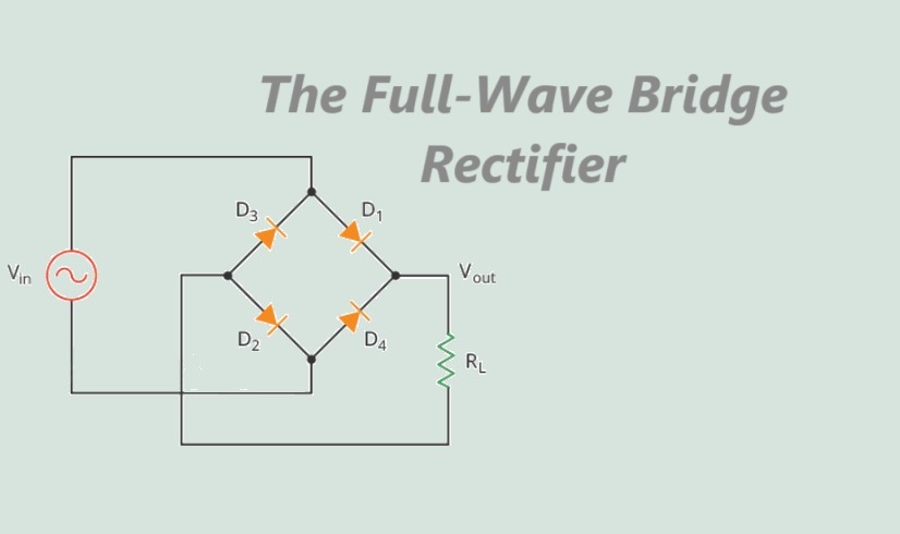
Circuit Diagram of bridge rectifier circuit is given below:

This circuit works by dealing with one half of the cycle at a time.
When the source’s voltage is positive during one half of the cycle, diodes D1 and D2 let the current flow while D3 and D4 block it. This makes a positive voltage across the load resistor. You can see the polarity marked with a plus and minus sign across the resistor.

During the next half-cycle,When the source voltage changes direction, D3 and D4 start conducting, and D1 and D2 stop. This still gives us a positive voltage across the load resistor, just like before.

No matter if the input voltage is positive or negative, the voltage across the load stays the same and the current flows in the same direction. This setup changes the AC input into a pulsating DC output.

If you find it tricky to remember how to place the diodes in a bridge rectifier circuit, there’s a simpler way to look at it. You can imagine all the diodes lying down horizontally and pointing in the same direction. It’s the same circuit, just easier to visualize.

DC Value of a Full-Wave Signal
Because a bridge rectifier produces a full-wave output, t


This formula says that the DC value of a full-wave signal is roughly 63.6% of its peak value. So, if the highest point of the signal is 10 volts, the average DC voltage will be around 6.36 volts.
When you use a DC voltmeter to measure a half-wave signal, the reading you get will match this average DC value.
A Second-order Approximation

Output Frequency
The full-wave rectifier flips each negative half cycle, making it positive, so it doubles the number of positive half cycles. This means the full-wave output has twice as many cycles as the input. So, the frequency of the full-wave signal is double the input frequency.

For example, if the line frequency is 60Hz, the output frequency will be 120Hz.
Filtering the Output of a Rectifier
The output of a full-wave rectifier is like a rollercoaster—it goes up, hits a peak, then comes back down to zero.
But what we really want is a smooth ride, like a straight road, with no bumps or ups and downs, just like what we get from a battery.
To make the voltage smooth and constant, we use something called a smoothing capacitor. It’s like a shock absorber for the voltage, making it steady and free of any bumps or ripples. We connect this capacitor across the load resistor to smooth out the voltage.

At the beginning, the capacitor is empty. When the input voltage starts rising during the first quarter-cycle, diodes D1 and D2 allow current to flow, so the capacitor starts filling up. It keeps charging until the input voltage reaches its highest point, which is the peak value. At this moment, the voltage across the capacitor matches the peak voltage (Vp).
Once the input voltage starts to drop after reaching its peak, the voltage across the capacitor stays higher than the input voltage. This turns off the diodes because they only let current flow in one direction.
Now that the diodes are off, the capacitor starts to discharge through the load resistor, providing power to the load, until the next peak comes along.
When the next peak arrives, diodes D3 and D4 briefly conduct, allowing the capacitor to recharge back to the peak voltage value. This process repeats with each cycle of the input signal, keeping the voltage across the capacitor relatively constant and smoothing out the output voltage.

Disadvantage
The only downside of the bridge rectifier is that the output voltage is a bit lower than the input voltage—about 1.4 volts less due to the two diode drops.
This drawback becomes more noticeable when the input voltage is very low. For example, if the source voltage peaks at just 5 volts, the load voltage will be around 3.6 volts. But if the source voltage peaks at 100 volts, the difference caused by the diode drops is hardly noticeable, and the load voltage will be close to what we expect from a perfect full-wave voltage.
Application of The Full-Wave Bridge Rectifier
The full-wave bridge rectifier has several applications across different industries and fields:
1. Power Supplies: One of the most common applications is in power supplies for electronic devices. It converts AC power from the mains into DC power suitable for powering electronic circuits.
2. Battery Chargers: Full-wave bridge rectifiers are used in battery chargers to convert AC power from the mains into DC power for charging batteries in devices such as smartphones, laptops, and electric vehicles.
3. Motor Control: In motor control circuits, full-wave bridge rectifiers are used to convert AC power into DC power to drive motors in appliances, industrial equipment, and automotive applications.
4. LED Lighting: Full-wave bridge rectifiers are used in LED lighting systems to convert AC power from the mains into DC power to drive the LEDs.
5. Audio Amplifiers: In audio amplifier circuits, full-wave bridge rectifiers are used to convert AC power from the mains into DC power to power the amplifier circuitry, providing clean and stable power for audio reproduction.
Overall, the full-wave bridge rectifier is a versatile component widely used in various applications where converting AC power into DC power is necessary.


