
ESP8266 NodeMCU with RCWL-0516 Microwave Radar Proximity Sensor (Arduino IDE)
What is RCWL-0516 Microwave Radar Proximity Sensor
The RCWL-0516 Microwave Radar Sensor module has been designed as an alternative to the common PIR motion sensors widely used in burglar alarms and security lights. Like the PIR sensor, this sensor also detects only movements within its detection range.
But instead of sniffing the blackbody radiation from a moving person, this sensor uses a “microwave Doppler radar” technique to detect moving objects. It has a sensitivity range of ~1 meters. When triggered, its TTL-level output (OUT) pin will switch from LOW (0 V) to HIGH (3.3 V) for a finite time (2 to 3 s) before returning to its idle (LOW) state.
This flexible sensor module can easily be used in conjunction with many microcontrollers and even without a microcontroller at all. It can handle power supply inputs anywhere from 4 to 28 V.
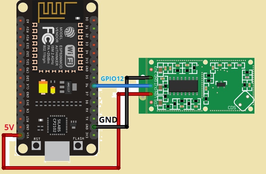
Connecting the RCWL-0516 Microwave Radar Proximity Sensor to the ESP8266
| RCWL-0516 Sensor | ESP8266 |
| 3V3 | don’t connect |
| GND | GND |
| OUT | GPIO12 (or any other GPIO of your choice) |
| VIN | VIN (or a voltage between 4 and 28V) |
| CDS | don’t connect |

Arduino Sketch
The code below should be copied into your Arduino IDE. This illustration is really simple. When motion is detected, it simply reads the sensor’s output, publishes it in the serial monitor, and turns on the ESP8266’s built-in LED in accordance (the LED is on when motion is detected).
// Keep keep mind that the built-in LED uses reversed logic if you're using it for testing.
// (HIGH=LOW, and LOW=HIGH)
int led = 2;               // the pin that the LED is interface to
int sensor = 12;           // the pin that the sensor is interface to
int state = LOW;           // by default, no motion detected
int val = 0;               // variable to store the sensor status (value)

void setup() {
  pinMode(led, OUTPUT);       // initalize LED as an output
  pinMode(sensor, INPUT);     // initialize sensor as an input
  Serial.begin(115200);       // initialize serial
}

void loop(){
  val = digitalRead(sensor);   // read sensor value
  if (val == HIGH) {           // check if the sensor is HIGH
    digitalWrite(led, HIGH);   // turn LED ON

    if (state == LOW) {
      Serial.println("Motion detected!");
      state = HIGH;       // update variable state to HIGH
    }
  }
  else {
    digitalWrite(led, LOW); // turn LED OFF

    if (state == HIGH){
      Serial.println("No Motion!");
      state = LOW;       // update variable state to LOW
    }
  }
}
Code Explanation
We’re using the ESP8266 built-in LED that is connected to GPIO2, but you can also connect a physical LED to any other GPIO, just change the code accordingly.
int led = 2; // the pin that the LED is attached toWe’re connecting the output of the sensor to GPIO 12, but you can use any other digital GPIO.
int sensor = 12; // the pin that the sensor is attached toThe state variable stores the current state of the output pin of the sensor and it is initially set to LOW.
int state = LOW; // by default, no motion detectedThe val variable will store the status (value) of the sensor’s digital output, either HIGH or LOW.
int val = 0; // variable to store the sensor status (value)Basically, val is used to temporarily store the real-time output value of the sensor, while state is used to keep track of whether motion has been detected or not over time.
In the setup(), set the LED as an output and the sensor as an input. Also, initialize the Serial Monitor at a baud rate of 115200.
void setup() {
  pinMode(led, OUTPUT);      // initalize LED as an output
  pinMode(sensor, INPUT);    // initialize sensor as an input
  Serial.begin(115200);        // initialize serial
}
In the loop(), we start by reading the sensor’s digital output (HIGH or LOW) and store it in the val variable.
val = digitalRead(sensor); // read sensor valueIf the sensor’s output is HIGH (motion detected), the LED turns on.
if (val == HIGH) {               // check if the sensor is HIGH
  digitalWrite(led, HIGH);   // turn LED ON
Remember
: ESP8266 built-in LED works with inverted logic, so you need to write LOW to turn it on and HIGH to turn it off. If you’re using a regular LED connected to that GPIO, it works with the “regular” logic.
Then, we check if the previous status was LOW. If so, it means the state has changed and that motion has been detected. We print a message in the Serial Monitor and change the state variable to HIGH.
if (state == LOW) {
  Serial.println("Motion detected!");
  state = HIGH;       // update variable state to HIGH
}
If the sensor’s output is LOW (no motion detected), we turn the LED off.
else {
   digitalWrite(led, LOW); // turn LED OFF
If the previous state was HIGH and, if now the state is LOW, it means motion has stopped, and we can set the state variable to LOW.
if (state == HIGH){
  Serial.println("No Motion");
  state = LOW;       // update variable state to LOW
}
Output
Upload the code and open the Serial Monitor. Now Reset your board.
Wave your hand in front of the motion sensor. You should get a “Motion detected” message followed by a “No Motion” message after two seconds. Additionally, the on-board LED will light up when motion is detected.


