
Radxa Zero | GPIO Pinout | Specs
Radxa Zero is an ultra thin SBC in small form factor with powerful performance based on Amlogic S905Y2. It can run Android and selected Linux distributions. Radxa Zero features a quad core 64-bit ARM processor, up to 4GB 32bit LPDDR4 memory, HDMI output at 4K@60, WiFi and Bluetooth connectivity, USB 3.0, and 40-pin GPIO header. Additionally, the power port can also be used for USB 2.0 OTG to connect more peripheral.
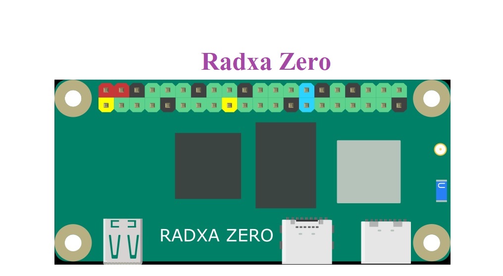
Radxa Zero Hardware & Main Board
 Power
Power
The Radxa Zero is designed to be a Single Board Computer with low power consumption. It supports the following power input:
- USB PD or QC power adapter which support 5V, 1A or higher output
- Power adapter with fixed 5V DC voltage
- USB port on PC or laptop
- 5V DC power from the GPIO PIN 2 & 4
The max power consumption of Radxa Zero without USB peripheral is 3.3W.
Processor
The SoC used in Radxa Zero is Amlogic S905Y2. The main system CPU is a quad-core ARM Cortex-A53 CPU with unified L2 cache to improve system performance. In addition, the Cortex-A53 CPU includes the NEON SIMD co-processor to improve software media processing capability. The graphic subsystem consists of two graphic engines and a flexible video/graphic output pipeline. The ARM G31 MP2 GPU supports OpenGL ES 3.2, Vulkan 1.0 and OpenCL 2.0, while the 2.5D graphics processor handles additional scaling, alpha, rotation and color space conversion operations.

Networking
Radxa Zero supports wireless network via the on board WiFi/BT modules.
For Radxa Zero model with 512MB or 1GB memory, it comes with AP6212 module. The wireless module complies with IEEE 802.11 b/g/n standard and it can achieve up to a speed of 72.2Mbps with single stream in 802.11n draft, 54Mbps as specified in IEEE 802.11g, or 11Mbps for IEEE 802.11b to connect to the wireless LAN. It also provides Bluetooth V4.0(HS) with integrated Class 1.5 PA and Low Energy (BLE) support.
For Radxa Zero model with 2GB or 4GB memory, it comes with AP6256 module. The wireless module complies with IEEE 802.11 a/b/g/n/ac standard and it can achieve up to a speed of 433.3Mbps with single stream in 802.11ac draft to connect to the wireless LAN. It also supports Bluetooth V5.0+EDR with integrated PA for Class 1.5 and Low Energy (BLE).
T variant SKU also has a u.FL connector in place of onboard antenna. This allows the use of external antenna, so when Radxa Zero is placed in an industrial style metal enclosure, the wireless communication is unaffected.
USB
The Radxa Zero has two USB-C connectors. The one closer to the short edge of the board is for USB 2.0 OTG and power, and the other one is for USB 3.0 HOST. When the USB BOOT button is pressed, OTG port can also be used to perform some low level operation, such as sideloading binary blob.
The USB 3.0 Type-C supports 5Gbps speed. A USB-C hub is recommend to connect traditional USB Type-A devices and on some hubs also with integrated Ethernet. None of the USB-C ports implements HDMI/DP Alternate Mode, so there is no native video output.
microSD Interface
The microSD card can be used as a system storage or an external storage. When using as system storage, card with at least 8GB is commanded. When using as external storage, card size up to 128GB are supported.
The microSD interface pinout is specified below:
| Pin# | Name |
|---|---|
| 1 | SDMMC0_D2 |
| 2 | SDMMC0_D3 |
| 3 | SDMMC0_CMD |
| 4 | VCC3V3_SYS |
| 5 | SDMMC0_CLK |
| 6 | GND |
| 7 | SDMMC0_D0 |
| 8 | SDMMC0_D1 |
| 9 | SDMMC0_DET_L |
| 10 | GND |
| 11 | GND |
| 12 | GND |
| 13 | GND |
eMMC (on selected models)
Radxa Zero with 2GB or 4GB of memory also has a high performance eMMC module. Different sizes are available: 8GB/16GB/32GB/64GB/128GB. Our eMMC modules meet eMMC 5.0 standard and support HS400 mode.
HDMI
The Radxa Zero has one micro HDMI connector. For HDMI, the maximum resolution is 4K@60Hz. Any HDMI monitor should work as a display for Zero.
This HDMI port also supports Consumer Electronics Control (CEC) function. Using Zero connected to a CEC compatible TV, you can use the CEC related programs such as cec-client tool to control the TV inputs and other properties.
The HDMI interface pinout is defined below:
| Pin# | Name |
|---|---|
| 1 | HDMI_TX2P |
| 2 | GND |
| 3 | HDMI_TX2N |
| 4 | HDMI_TX1P |
| 5 | GND |
| 6 | HDMI_TX1N |
| 7 | HDMI_TX0P |
| 8 | GND |
| 9 | HDMI_TX0N |
| 10 | HDMI_TXCP |
| 11 | GND |
| 12 | HDMI_TXCN |
| 13 | PORT_CEC |
| 14 | NC |
| 15 | DDC_SCL |
| 16 | DDC_SDA |
| 17 | GND |
| 18 | VCC5V0_HDMI |
| 19 | HDMI_HPD |
Specifications
| Model | Radxa Zero 512MB/1GB | Radxa Zero 2GB/4GB | |
|---|---|---|---|
| Processor | 64bits quad core processor Amlogic S905Y2 Quad Cortex-A53@1.8GHz ARM G31 MP2 GPU, supporting OpenGL ES 3.2, Vulkan 1.0, and OpenCL 2.0. |
||
| Memory | LPDDR4 32bit LPDDR4@3200Mb/s |
||
| Storage | microSD card (microSD slot supports up to 128 GB microSD card) | on board 8GB eMMC(2GB ram model) or 16GB/32GB/64GB/128GB eMMC(4GB ram model) microSD card (microSD slot supports up to 128 GB microSD card) |
|
| Display | HDMI 2.0 up to 4K@60 | ||
| Camera | None | ||
| Wireless | 802.11 a/b/g/n (WiFi 4) Bluetooth 4.0 with on board antenna (optional external antenna) |
802.11 ac (WiFi 5) Bluetooth 5.0 with on board antenna (optional external antenna) |
|
| USB | 1 x USB 2.0 Type-C OTG & Power combo port 1 x USB 3.0 Type-C HOST |
||
| IO | 40-pin expansion header 2 x UART 2 x SPI bus 3 x I2C bus 1 x PCM/I2S 1 x SPDIF 2 x PWM 1 x ADC 6 x GPIO 2 x 5V DC power in 2 x 3.3V DC power in |
||
| Others | One button for force USB boot or firmware upgrading | ||
| Power | USB-C, 5V/1A | ||
| Size | 66mm x 30.5mm | ||
General purpose input-output (GPIO) connector
Radxa Zero has a 40-pin expansion header. Each pin is distinguished by color.

More details about 40-pin Header
- Pins marked with orange color are designed for debug console.
- I2C: x3; I2C_EE_M1 (/dev/i2c-1), I2C_EE_M3 (/dev/i2c-3), I2C_AO_M0 (/dev/i2c-4)
- PWM: x3; PWMAO_A, PWM_C
- SPI: x2; SPI_A (/dev/spi0.0), SPI_B(/dev/spi1.0)
- UART: x3; UART_AO_A (/dev/ttyAML0), UART_AO_B (/dev/ttyAML1), UART_EE_C (/dev/ttyAML4)
- Pin#22 (GPIOC_7) and Pin#36 (GPIOH_8) are open drain pins. This means for input they need to connected to either GND or VCC (floating state is undefined), for output they will need external pull up. Additionally GPIOH_8 runs on 5V logic.
GPIO number
- GPIOs are grouped in two banks, GPIO AO domain and GPIO EE domain
- AO domain: GPIOAO_0 – GPIOAO_11
- EE domain: GPIOA_14 – GPIOA_15 | GPIOH_0 – GPIOH_8 | GPIOX_0 – GPIOX_19
- UARTs
- AO domain: UARTAO_A | UARTAO_B
- EE domain: UART_A | UART_B | UART_C
| GPIO Chip | GPIO Name | Base | Offset | Formula |
|---|---|---|---|---|
| First | GPIOAO_x | 412 | 0-11 | Base + Offset |
| First | GPIOE_x | 424 | 0-2 | Base + Offset |
| Second | GPIOZ_x | 427 | 0-15 | Base + Offset |
| Second | GPIOH_x | 443 | 0-8 | Base + Offset |
| Second | BOOT_x | 452 | 0-15 | Base + Offset |
| Second | GPIOC_x | 468 | 0-7 | Base + Offset |
| Second | GPIOA_x | 476 | 0-15 | Base + Offset |
| Second | GPIOX_x | 492 | 0-19 | Base + Offset |
Take GPIOX_10 as an example.
The base is 492 and the offset is 10. So the GPIOX_10’s GPIO number is 492+10=502.
Reference : https://wiki.radxa.com/Zero


Pingback: Getting Started with Radxa Zero - IoTbyHVM - Bits & Bytes of IoT
Pingback: Getting Started with Radxa Zero – apalgorithm.com