
Introduction to the CC3200MOD LaunchPad
Introduction to the CC3200MOD LaunchPad, GPIO Interfacing, Peripheral Programming, and Interfacing with Sensors, GPS, GSM, Bluetooth, and Stepper Motors
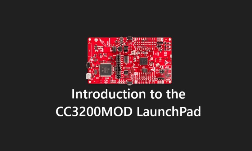
The Texas Instruments CC3200MOD LaunchPad is a versatile development platform designed for Internet of Things (IoT) applications. Built around the CC3200MOD module, it integrates a powerful ARM Cortex-M4 microcontroller with an onboard Wi-Fi network processor, making it an excellent choice for projects requiring wireless connectivity, sensor interfacing, and peripheral control. This article provides an in-depth introduction to the CC3200MOD LaunchPad, exploring its architecture, GPIO interfacing, peripheral programming (UART, ADC, SPI, I2C), and practical applications like interfacing with sensors (on-board and external), GPS, GSM, Bluetooth modules, and stepper motors.
1. Overview of the CC3200MOD LaunchPad
The CC3200MOD LaunchPad is part of Texas Instruments’ SimpleLink family, designed to simplify IoT development. At its core is the CC3200MOD, a single-chip solution combining a 32-bit ARM Cortex-M4 microcontroller running at 80 MHz and a dedicated Wi-Fi network processor. This dual-processor architecture offloads Wi-Fi communication tasks from the main MCU, allowing developers to focus on application logic.
Key features of the CC3200MOD LaunchPad include:
- Microcontroller: ARM Cortex-M4 with 256 KB RAM, 1 MB on-chip flash, and support for external serial flash.
- Wi-Fi: On-chip 802.11 b/g/n with station, access point, and Wi-Fi Direct modes.
- Peripherals: GPIO pins, UART, SPI, I2C, ADC, PWM, and timers.
- On-board Hardware: Temperature sensor, 3-axis accelerometer, LEDs, push buttons, and a USB interface for programming and debugging.
- Power Options: USB-powered or external supply with low-power modes for battery-operated applications.
The LaunchPad follows the BoosterPack pinout standard, enabling compatibility with a wide range of add-on modules. Its Energia IDE support (based on the Arduino framework) and TI’s Code Composer Studio make it accessible to beginners and advanced developers alike.
2. GPIO Interfacing
General Purpose Input/Output (GPIO) pins are the foundation of hardware interfacing on the CC3200MOD LaunchPad. The board provides up to 27 GPIO pins, depending on multiplexing with other peripherals. These pins can be configured as inputs or outputs, with features like pull-up/pull-down resistors, interrupt capability, and digital I/O functionality.
GPIO Basics
- Configuration: GPIOs are controlled via registers in the CC3200MOD’s memory map. The TI DriverLib library simplifies this with functions like
PinModeSet()andGPIODirModeSet(). - Output Example: To turn on an LED connected to GPIO10 (mapped to pin P1.9 on the LaunchPad), you’d write:
  PinModeSet(PIN_10, PIN_MODE_0); // Set as GPIO
  GPIODirModeSet(GPIOA1_BASE, GPIO_PIN_2, GPIO_DIR_MODE_OUT); // GPIO10 as output
GPIOPinWrite(GPIOA1_BASE, GPIO_PIN_2, GPIO_PIN_2); // Set high- Input Example: To read a push button on GPIO11 (P1.10):
  PinModeSet(PIN_11, PIN_MODE_0); // Set as GPIO
  GPIODirModeSet(GPIOA1_BASE, GPIO_PIN_3, GPIO_DIR_MODE_IN); // GPIO11 as input
  uint8_t state = GPIOPinRead(GPIOA1_BASE, GPIO_PIN_3); // Read state
Interrupts
GPIOs support edge-triggered interrupts (rising, falling, or both). This is useful for detecting button presses or sensor events:
GPIOIntTypeSet(GPIOA1_BASE, GPIO_PIN_3, GPIO_FALLING_EDGE); // Falling edge interrupt
GPIOIntEnable(GPIOA1_BASE, GPIO_PIN_3); // Enable interrupt
GPIO interfacing forms the backbone for connecting external devices like LEDs, switches, and sensors, making it a critical skill for CC3200MOD projects.
3. Peripheral Programming
The CC3200MOD LaunchPad supports a rich set of peripherals, enabling communication with external hardware. Let’s explore UART, ADC, SPI, and I2C programming.
UART (Universal Asynchronous Receiver/Transmitter)
UART facilitates serial communication with devices like GPS and GSM modules. The CC3200MOD has two UART modules (UART0 and UART1).
- Setup: Configure baud rate, parity, and data bits using
UARTConfigSetExpClk(). - Example: Sending “Hello” at 115200 baud via UART1 (P1.3 TX, P1.4 RX):
  SysCtlPeripheralEnable(SYSCTL_PERIPH_UART1);
  UARTConfigSetExpClk(UART1_BASE, 80000000, 115200, (UART_CONFIG_WLEN_8 | UART_CONFIG_STOP_ONE | UART_CONFIG_PAR_NONE));
  UARTEnable(UART1_BASE);
  const char *msg = "Hello";
  while (*msg) UARTCharPut(UART1_BASE, *msg++);
ADC (Analog-to-Digital Converter)
The ADC converts analog signals (e.g., from sensors) to digital values. The CC3200MOD has a 12-bit ADC with four channels.
- Setup: Enable the ADC and configure a channel (e.g., ADC_CH_0 on P60).
- Example: Reading an analog sensor:
  SysCtlPeripheralEnable(SYSCTL_PERIPH_ADC0);
  ADCSequenceConfigure(ADC0_BASE, 0, ADC_TRIGGER_PROCESSOR, 0);
  ADCSequenceStepConfigure(ADC0_BASE, 0, 0, ADC_CTL_CH0 | ADC_CTL_END);
  ADCSequenceEnable(ADC0_BASE, 0);
  ADCProcessorTrigger(ADC0_BASE, 0);
  uint32_t value;
  while (!ADCIntStatus(ADC0_BASE, 0, false));
  ADCSequenceDataGet(ADC0_BASE, 0, &value); // 0-4095 range
SPI (Serial Peripheral Interface)
SPI is a high-speed synchronous interface for devices like displays and sensors. The CC3200MOD has two SPI modules.
- Setup: Configure as master or slave, set clock speed, and define data format.
- Example: Sending data to an SPI device:
  SysCtlPeripheralEnable(SYSCTL_PERIPH_SSI0);
  SSIConfigSetExpClk(SSI0_BASE, 80000000, SSI_FRF_MOTO_MODE_0, SSI_MODE_MASTER, 1000000, 8);
  SSIEnable(SSI0_BASE);
  SSIDataPut(SSI0_BASE, 0xAA); // Send byte 0xAA
I2C (Inter-Integrated Circuit)
I2C is a two-wire bus for connecting sensors and modules. The CC3200MOD supports multiple I2C modules.
- Setup: Configure as master, set clock speed (e.g., 100 kHz or 400 kHz).
- Example: Reading from an I2C sensor (e.g., address 0x48):
  SysCtlPeripheralEnable(SYSCTL_PERIPH_I2C0);
  I2CMasterInitExpClk(I2C0_BASE, 80000000, false); // 100 kHz
  I2CMasterSlaveAddrSet(I2C0_BASE, 0x48, false); // Write mode
  I2CMasterDataPut(I2C0_BASE, 0x00); // Register address
  I2CMasterControl(I2C0_BASE, I2C_MASTER_CMD_SINGLE_SEND);
4. On-board and External Sensor Interfacing
The CC3200MOD LaunchPad includes on-board sensors (temperature sensor and accelerometer), but its real power lies in interfacing with external sensors.
On-board Sensors
- Temperature Sensor: Connected via I2C (TMP006), it measures ambient temperature. Use the I2C peripheral to read raw data and convert it to Celsius.
- Accelerometer: A 3-axis BMA222E (I2C) provides motion data. Read X, Y, Z values to detect tilt or movement.
External Sensors
- DHT22 (Temperature/Humidity): Uses a single GPIO pin for digital communication. Timing-critical bit-banging is required to decode its protocol.
- MQ-2 (Gas Sensor): An analog sensor connectable to the ADC. Map the 0-4095 ADC reading to gas concentration using calibration data.
- Ultrasonic Sensor (HC-SR04): Uses GPIO for trigger and echo. Measure pulse width to calculate distance:
  GPIOPinWrite(GPIOA1_BASE, GPIO_PIN_2, GPIO_PIN_2); // Trigger high
  SysCtlDelay(800); // 10 µs pulse
  GPIOPinWrite(GPIOA1_BASE, GPIO_PIN_2, 0); // Trigger low
  // Measure echo pulse width using timer
5. GPS Interfacing
GPS modules (e.g., NEO-6M) provide location data via UART. Connect TX/RX pins to the CC3200MOD’s UART1 and parse NMEA sentences (e.g., $GPGGA).
- Setup: Baud rate is typically 9600.
- Code: Read and extract latitude/longitude:
  char buffer[80];
  while (UARTCharsAvail(UART1_BASE)) {
      buffer[i++] = UARTCharGet(UART1_BASE);
      if (buffer[i-1] == '\n') {
          if (strncmp(buffer, "$GPGGA", 6) == 0) {
              // Parse latitude, longitude
          }
      }
  }
6. GSM Interfacing
GSM modules (e.g., SIM800L) enable cellular communication. They use UART and AT commands.
- Setup: Connect TX/RX to UART1, power with an external 3.7-4.2V supply.
- Example: Send an SMS:
  UARTPuts(UART1_BASE, "AT+CMGF=1\r", -1); // Text mode
  UARTPuts(UART1_BASE, "AT+CMGS=\"+1234567890\"\r", -1); // Phone number
  UARTPuts(UART1_BASE, "Hello from CC3200!\x1A", -1); // Message + Ctrl+Z
7. Bluetooth Interfacing
Bluetooth modules (e.g., HC-05) use UART for pairing with devices.
- Setup: Connect to UART1, configure baud rate (default 9600).
- Example: Send data to a paired device:
UARTPuts(UART1_BASE, "Bluetooth Test", -1);8. Stepper Motor Control
Stepper motors require precise GPIO sequencing or PWM. Use four GPIO pins for a unipolar stepper or a driver like L298N.
- Setup: Define a step sequence (e.g., full-step mode).
- Code: Rotate a stepper:
  uint8_t steps[4] = {0x09, 0x0C, 0x06, 0x03}; // A-B sequence
  for (int i = 0; i < 200; i++) { // 200 steps = 1 revolution
      GPIOPinWrite(GPIOA1_BASE, 0x0F, steps[i % 4]);
      SysCtlDelay(80000); // Delay for speed control
  }
9. Practical Applications
Combining these features, you can build:
- IoT Weather Station: Use DHT22, Wi-Fi, and cloud upload.
- Smart Vehicle Tracker: Integrate GPS, GSM, and accelerometer.
- Home Automation: Control stepper motors and sensors via Bluetooth/Wi-Fi.
10. Conclusion
The CC3200MOD LaunchPad is a powerful platform for IoT and embedded systems development. Its GPIO versatility, rich peripheral set, and wireless capabilities make it ideal for interfacing with sensors, GPS, GSM, Bluetooth, and motors. With tools like Energia and TI’s SDK, developers can prototype complex projects efficiently. Whether you’re a beginner blinking an LED or an expert building a connected device, the CC3200MOD offers endless possibilities.


