
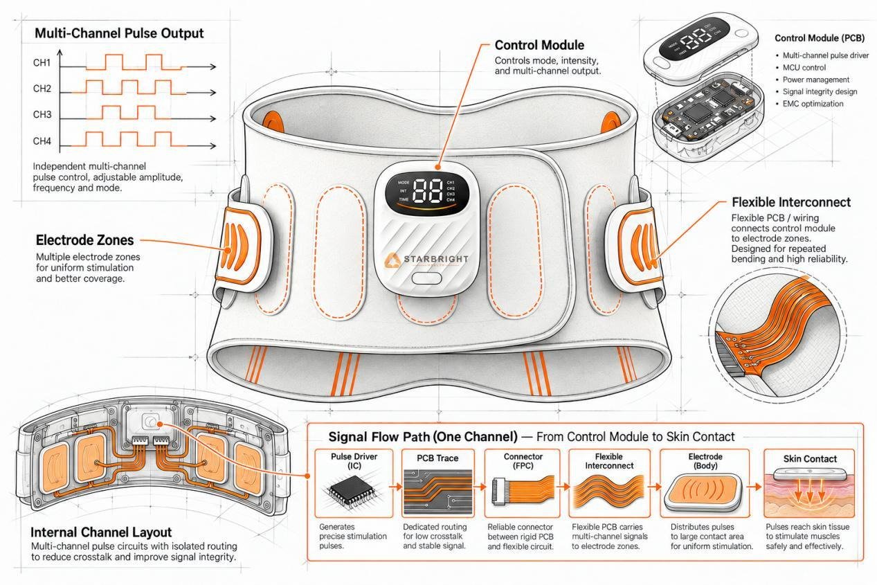
Flexible Waist Belt PCB Design:Multi-Channel Pulse Circuit Signal Integrity and EMC Optimization

A flexible massage belt presents a unique PCB design challenge: its electrical load changes during real use.
As the user tightens the belt, moves, or changes posture, electrode pressure, skin contact, and belt bending all change. These variations can affect the electrical load seen by each pulse channel and influence output consistency.
At the same time, multiple pulse channels may operate together. If PCB power paths, return currents, connector design, or channel spacing are not properly controlled, the system may experience waveform distortion, channel coupling, unstable output, or interference with control and wireless circuits.
This is why signal integrity and EMC optimization are essential in flexible waist belt PCB design. The goal is not only to generate pulse signals, but to maintain stable output across the full path:
Pulse Driver → PCB Trace → Connector → Flexible Interconnect → Electrode → Skin Contact
Grounding, power integrity, channel isolation, filtering, routing, and mechanical connection design must therefore be optimized as one complete system.
1. PCB Architecture for a Flexible Massage Belt
1.1 Complete PCB System Architecture
A typical flexible massage belt electronic system includes the main control circuit, power management, multi-channel pulse drivers, electrode interfaces, user controls, sensors, and optional wireless communication modules.
The PCB acts as the central platform connecting these functions. Power must be distributed to both low-voltage control circuits and pulse output stages, while control signals coordinate different massage zones, operating modes, intensity levels, and protection functions.
Because the belt has limited internal space, the PCB layout must balance compactness with electrical isolation. Pulse-driving circuits should be separated from sensitive control and communication areas, while connectors to the flexible electrode sections should be positioned to reduce both signal loss and mechanical stress.
1.2 Multi-Channel Pulse Circuits: The Core of the PCB System
The multi-channel pulse circuit is a key part of a massage belt PCB.
Different electrode zones may operate independently or in coordinated patterns, requiring separate pulse channels for timing, sequence, and intensity control.
When multiple channels switch at the same time, poor power distribution, grounding, or routing can cause channel interference, leading to unstable or inconsistent output.
The PCB should keep each channel electrically isolated while sharing the same power and control system.
1.3 Importance of EMC Optimization
Pulse circuits contain rapidly changing voltage and current signals, which can generate both conducted and radiated interference.
Inside a flexible massage belt, this interference may affect low-level control signals, sensor readings, buttons, displays, or wireless communication modules. In compact designs, the distance between the pulse output stage and sensitive circuits can be very small, increasing the risk of coupling.
EMC optimization therefore needs to begin during the PCB layout stage rather than after prototype testing. Proper circuit partitioning, grounding, filtering, and current-loop control can significantly reduce interference before the product reaches certification and mass production.
2. How Multi-Zone Massage Affects Multi-Channel Pulse PCB Design
2.1 Independent Pulse Output for Different Massage Zones
A flexible waist belt, including EMS body shaping belts, usually covers several body-contact areas rather than a single fixed point. These zones may be arranged around the center, left, and right sides of the waist, depending on the product structure.
Independent pulse channels allow different areas to operate separately, making it possible to create multiple massage patterns instead of sending the same output to every electrode at the same time.
From a PCB perspective, each channel needs a controlled signal path from the pulse driver to its corresponding connector and electrode. The design should minimize unwanted interaction between channels so that adjusting one massage zone does not noticeably affect another.
2.2 Impact of Body Contact Impedance on Pulse Output
Unlike a fixed electronic load, a massage belt’s electrode contact changes with skin condition, belt tightness, body movement, placement, and contact area. These changes affect the load seen by the pulse output circuit.
If the output stage is too sensitive to load variation, the same setting may produce different sensations under different wearing conditions. The PCB must maintain stable pulse output across normal contact changes, placing higher demands on power stability, protection, feedback, and output-stage design.
2.3 Output Consistency During Multi-Channel Operation
When multiple massage zones operate at the same time, the total power load increases. If the power supply or PCB power paths cannot respond fast enough, voltage fluctuations can cause one channel to affect another.
Low-impedance power paths, local energy storage, proper power distribution, and channel isolation help maintain consistent multi-channel output. This consistency is especially important in mass production, where the same intensity setting should perform similarly across units and batches.
3. Signal Integrity from PCB to Massage Electrodes
3.1 Complete Pulse Signal Path from PCB to Electrode
The pulse signal travels through the complete output path:
Pulse Driver → PCB Trace → Connector → Flexible Wire/FPC → Massage Electrode
Each section can affect waveform quality. Long traces, narrow copper paths, poor connectors, and flexible interconnects can add resistance, capacitance, and inductance, causing signal loss or pulse distortion.
Signal integrity should be evaluated across the entire output path, not just the driver circuit.

3.2 Crosstalk and Channel Isolation Between Electrodes
In a compact waist belt, pulse traces and electrode connections are often routed close together.
Fast transitions on one channel can couple noise into nearby traces, creating unwanted pulses in other massage zones.
Greater spacing, shorter parallel runs, optimized return paths, and separation from sensitive control traces help reduce crosstalk.
In multi-channel systems, channel isolation depends on both circuit design and PCB routing.
3.3 Impact of Belt Flexing and Body Movement on Connection Stability
A flexible massage belt is repeatedly bent, tightened, loosened, and repositioned during use.
This stresses PCB edges, connectors, solder joints, flexible cables, and electrode interfaces, which can increase contact resistance or cause intermittent connections over time.
PCB mounting points and connectors should include mechanical reinforcement and strain relief, and stay away from high-flex areas.
For FPCs or flexible wiring, bend radius and flex life should also be considered in the mechanical design.
4. EMC Optimization for Multi-Channel Pulse Circuits
4.1 Why Pulse Massage Signals Generate EMI
Pulse circuits switch rapidly between electrical states, creating electromagnetic interference as voltage and current change.
In a multi-channel massage belt, several outputs may switch at different times, increasing noise on shared power and ground paths.
Large current loops, long output traces, and poor switching-component placement can further increase emissions.
EMI control requires reducing both the noise source and its coupling path.
4.2 PCB Partitioning for Pulse, Control, and Wireless Circuits
Clear functional partitioning is one of the most effective EMC measures.
Pulse drivers and high-current switching circuits should be separated from control, sensing, and wireless sections whenever possible.
Sensitive signals should avoid high-noise pulse areas, while antennas should stay away from switching nodes, high-current traces, and noisy return paths.
This is especially important in compact single-PCB designs.
4.3 Grounding, Filtering, and Return Path Design
EMC performance can also be affected by components outside the rigid PCB.
Connectors, FPCs, and flexible wires may act as unintended coupling paths or radiating structures, especially when pulse signals travel over longer distances inside the belt. Parallel routing between pulse lines and sensitive signal traces should therefore be minimized.
Wireless modules and antennas should be placed away from pulse drivers, switching nodes, and high-current return paths. This reduces the risk of pulse noise degrading Bluetooth, 2.4 GHz, or other wireless communication performance.
EMC optimization must therefore extend from the PCB layout to the full electrical path of the wearable system.
Table: EMI Sources and EMC Optimization in Flexible Waist Belt PCB Design
| EMI Source | Coupling Path | Possible Effect | PCB / System Optimization |
| Fast pulse switching | Power and ground network | Control instability or signal noise | Short switching loops and local decoupling |
| Simultaneous multi-channel output | Shared power rails | Voltage fluctuation or channel interaction | Local energy storage and channel separation |
| Long pulse traces | Radiated and capacitive coupling | Crosstalk between channels | Shorter routing and increased spacing |
| Shared ground impedance | Common return path | Reference shift and unstable control | Controlled grounding and return-path design |
| Connector / FPC routing | Conducted or radiated coupling | Signal distortion or EMI increase | Optimized pin assignment and routing separation |
| Pulse circuit near wireless module | RF coupling | Reduced wireless range or unstable communication | Functional zoning and antenna clearance |
| Large current loop area | Magnetic field radiation | Increased radiated emissions | Minimized loop area and close return routing |
5. PCB Reliability and Validation for Wearable Use
5.1 Pulse Output Testing Under Different Body Loads
A massage belt should not be evaluated using only a single fixed electrical load.
Development testing should include different equivalent load conditions to simulate variations in electrode contact and wearing conditions.
Engineers can then observe whether pulse amplitude, timing, channel consistency, and protection behavior remain stable when the load changes.
This helps identify designs that appear stable under laboratory conditions but become inconsistent during actual use.
5.2 Flexing, Connector, and Electrode Interface Reliability Testing
Mechanical reliability is just as important as electrical performance.
Repeated bending and movement can affect connectors, FPCs, solder joints, and electrode contacts. Reliability testing should therefore simulate the flexing and movement that occurs during normal wearing.
Inspection should focus on intermittent connections, rising contact resistance, cracked solder joints, connector loosening, and signal instability after repeated mechanical stress.
These tests are particularly important for designs that place rigid PCB sections close to flexible belt structures.
5.3 Multi-Channel Operation and System-Level EMC Validation
Passing individual PCB tests does not guarantee that the complete massage belt will operate reliably.
Final validation should run multiple pulse channels together while monitoring control functions, wireless communication, sensor behavior, and power stability.
EMC testing should also be performed at system level because interference paths can change after the PCB, wiring, electrodes, housing, and battery are assembled into the final product.
Combining electrical, mechanical, and EMC validation provides a more realistic assessment of whether the design is ready for mass production.
Author Bio:
I’m Viva. I work with massage products, from waist and leg massagers to full-body massage devices. I pay attention not only to comfort and user experience, but also to the engineering behind them — including PCB design, pulse control, EMC, and manufacturing quality.
I look at massage products from both the product and manufacturing sides, and I share practical insights and industry observations on my LinkedIn. If you like talking shop about what makes a massage product tick, we’ll probably get along.


