
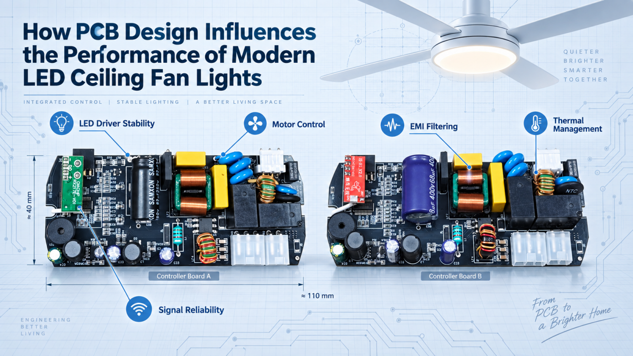
How PCB Design Influences the Performance of Modern LED Ceiling Fan Lights
As LED ceiling fan lights integrate BLDC motors, smart controls, and wireless functions, the PCB has become the core platform connecting multiple systems into one reliable solution.
A well-designed PCB must balance power efficiency, thermal management, signal integrity, and EMI control. Any design weakness may cause LED flicker, motor noise, control issues, or reduced product lifespan.
Therefore, understanding the impact of PCB design on system performance is essential for developing reliable ceiling fan light solutions.
1.1 From Mechanical to Electronic Systems
Early ceiling fans were built around mechanical structures. Speed control relied on inductors and pull-chain switches, while lighting was simply controlled through basic sockets and switches. The PCB mainly served as a wiring connection and had little impact on overall performance.
With the adoption of BLDC motors, LED lighting, and smart controls, modern LED ceiling fan lights have evolved into integrated electromechanical systems. The PCB is now the core platform that manages motor control, LED performance, power conversion, signal processing, and intelligent functions.
Industry return data indicates that over 80% of modern ceiling fan light failures are related to electronic systems .More than half of these failures are linked to PCB architecture issues, such as poor thermal management, improper circuit layout, and insufficient solder reliability. The focus has shifted from better motors to better PCBs.
1.2 Connecting Lighting, Motor, Power, and Control
Modern LED ceiling fan lights rely on PCB design to integrate power, motor, lighting, and smart control systems.
Two main PCB architectures are used:
Multi-board design: Separate PCBs handle power, motor drive, LED, and control functions. It offers flexible assembly but requires more wiring, which may increase signal loss, vibration risks, and EMI issues.
Single-board design: All functions are integrated into one PCB, improving reliability and reducing signal loss. However, it requires careful design of power routing, grounding, signal isolation, and safety spacing.
PCB architecture directly affects product stability. Proper design helps reduce heat loss, prevent LED flicker, and avoid control interference, ensuring efficient and reliable operation.
1.3 Managing Interactions Between Electronic Subsystems
PCB architecture coordinates electrical, thermal, and mechanical interactions to ensure stable ceiling fan light performance.
Key interactions include:
Electromagnetic Interaction: Motor drive and LED dimming can generate noise. Proper grounding, signal isolation, and EMI design help maintain control stability.
Thermal Interaction: Heat from power components can affect LED drivers and control modules. Optimized PCB layout and thermal management improve long-term reliability.
2. How Power Architecture and Power Integrity Affect System Stability
2.1 Power Requirements of Key Circuits
LED ceiling fan lights include three key circuits with different power characteristics, requiring different PCB designs for current capacity, routing, and safety spacing.
BLDC motor drive circuits are dynamic high-power loads (30–70W) with startup currents up to 3–5 times the rated current. PCB traces require sufficient current margin and optimized routing to prevent overheating and torque loss.
LED constant-current circuits require stable current control to avoid flicker and brightness variation. Clean grounding and separation from motor power paths help prevent noise interference.
MCU and remote control circuits are low-power, high-sensitivity systems. Independent power paths and filtering are needed to avoid switching noise and control failures.
Multi-board designs require voltage drop margins between boards, while high-voltage export models require strict safety spacing.
2.2 Voltage Regulation and Power Stability
PCB architecture directly affects power stability under voltage fluctuations and dynamic loads.
During fan speed changes or LED dimming, high-impedance power paths can cause voltage drops and performance instability. Shorter power paths, wider traces, and copper planes improve transient response.
Proper grounding separates power, signal, and LED circuits to reduce noise and maintain stable voltage references. Close placement of filtering components also improves ripple control and reliability.
2.3 Efficiency, Loss, and Thermal Management
Power losses generate heat, reducing efficiency and affecting component lifespan. PCB design is essential for controlling power loss and heat distribution.
Conduction loss increases with longer, thinner traces, while larger switching loops increase voltage spikes and EMI noise.
Optimized PCB design uses short power routes, large copper areas, thermal vias, and proper component placement to improve heat dissipation and long-term reliability.
3 LED Control PCB Design and Its Impact on Lighting Performance
3.1 LED Current Regulation
LED brightness and color stability depend on accurate forward current control, and PCB routing directly affects constant-current regulation accuracy.
Parasitic resistance in the current sensing path can add errors to the sensing resistor, causing output current deviation, uneven brightness, or reduced light output. If sensing traces are routed close to motor power lines, high-frequency noise can couple into the signal path, causing current fluctuation and visible flicker.
A proper PCB design routes sensing traces with ground shielding, follows a clean analog ground reference, and maintains sufficient separation from power areas to ensure stable current regulation.
3.2 PWM Dimming and CCT Control
Smooth PWM dimming and consistent color temperature (CCT) control depend on proper PCB signal and power routing.
Long PWM traces or routing near high-voltage power areas can cause signal distortion and duty-cycle errors, resulting in unstable dimming performance at low brightness levels. In dual-color LED designs, uneven PWM routing or different trace lengths can create timing differences, causing color shifts during adjustment.
Mismatch between cool and warm LED power paths can also create current imbalance and color temperature variation. Large PWM power loops may generate additional electromagnetic noise and interfere with wireless control circuits.
3.3 Power Integrity and Flicker Control
LED flicker is mainly caused by unstable current, often due to poor power integrity in shared motor-LED systems.
Motor startup and speed changes can create voltage fluctuations. High-impedance PCB traces or poor capacitor placement may cause LED current variation and visible flicker.
Shared grounding can also introduce noise. Without proper ground separation, motor switching currents may affect LED driver references and reduce stability.
For single-board designs, effective power routing and ground partitioning are essential to prevent flicker issues.
4 How Motor Control PCB Design Affects Speed, Airflow, and Noise Performance
4.1 DC and BLDC Motor Drivers
Traditional brushed DC motors have limitations such as noise, shorter lifespan, and interference. Modern ceiling fan lights mainly use BLDC motors, making PCB design critical for performance.
A BLDC driver PCB includes power switching, gate driving, and position sensing circuits. MOSFET layout, copper width, and gate routing affect thermal performance, switching stability, and EMI.
Accurate Hall sensor or back-EMF routing ensures proper commutation, preventing torque loss, speed fluctuation, and abnormal noise.
In single-board designs, motor power areas must be isolated from LED and control circuits. In multi-board designs, reliable connectors are essential for vibration resistance and long-term operation.
4.2 PWM Switching and Speed Control
BLDC motors use PWM control for speed adjustment, and speed accuracy depends on PCB power and signal routing.
Insufficient bus trace capacity or inadequate energy storage can cause voltage fluctuations during load changes, resulting in speed instability, especially at low-speed settings.
If speed feedback signals (Hall sensors or back-EMF sensing) are routed close to switching power lines, noise coupling may affect MCU calculations, causing control loop instability and speed drift.
PWM frequency selection must match the PCB power loop design and thermal capability. Higher switching frequencies allow smoother speed control but also increase switching losses and EMI.
4.3 Torque Ripple and Motor Noise
Electromagnetic noise is mainly caused by torque ripple, which is influenced by PCB driver design.
Uneven three-phase trace impedance can create current imbalance and commutation errors, leading to vibration and noise.
Reducing power loop inductance helps minimize voltage spikes and current harmonics.
PCB structure also affects noise performance. Proper component placement, board strength, and thermal connection to the housing help reduce vibration and improve stability.
5 How PCB Layout Affects Thermal Performance and EMI Control
5.1 Heat Generation from Power Components
MOSFETs, LED drivers, bridge rectifiers, and electrolytic capacitors are the main heat sources on a PCB.
MOSFET heat is mainly generated by switching losses. Since heat concentrates around the device junction, sufficient copper area and proper thermal paths are required to prevent excessive temperature rise, thermal protection triggering, or component failure.
Electrolytic capacitors are highly temperature-sensitive. Continuous exposure to high temperatures accelerates electrolyte degradation and shortens lifespan. In integrated PCB designs, poor thermal distribution can create local hot spots, transferring heat to sensitive components such as MCUs and wireless modules, causing performance drift.
5.2 Thermal Paths and Component Layout

PCB layout, copper areas, and thermal vias work together to create the main heat transfer path:
Component pad → PCB copper → Thermal vias → Metal housing
High-density thermal vias under power components help transfer heat from the top layer to larger copper areas and the metal housing for improved cooling.
Insufficient vias, small via sizes, or copper areas interrupted by routing can significantly increase thermal resistance. A proper layout places high-power components near PCB edges and mounting points to shorten heat paths, while keeping temperature-sensitive components, such as MCUs and wireless modules, away from heat sources.
Thermal isolation structures can also be added when needed to reduce heat transfer through the PCB substrate.
5.3 Grounding, Filtering, and EMI Control
EMI control depends on proper grounding, filtering, and power loop design.
Separate power, analog, and signal grounds, connecting them at a controlled point to reduce noise and ground loops.
Place EMI filters near the AC input and decoupling capacitors close to power devices to suppress interference.
Minimizing power loop areas with close positive and negative routing helps reduce radiated emissions.
6 How Smart Control Integration and System Design Affect Reliability
6.1 MCU and Wireless Integration
The MCU controls the system, while Bluetooth, WiFi, and 2.4GHz modules are sensitive to power noise.
Independent power regulation, proper grounding, and separation from high-power circuits help prevent crashes and wireless performance issues.
For multi-wireless systems, PCB layout should reduce frequency interference by isolating RF traces and crystal oscillators.
Single-board designs require clear functional separation and sufficient safety spacing to improve reliability.
6.2 Antenna Layout and Signal Integrity
PCB antenna design directly impacts wireless range and signal stability.
The antenna area requires sufficient clearance from metal traces, components, and screws, while keeping away from metal housings to avoid impedance mismatch and signal loss.
RF traces should maintain controlled 50Ω impedance and stay separated from power switching circuits to reduce interference.
For separate receiver boards, placing antennas in non-metallic areas such as lamp covers or grilles helps minimize shielding effects.
6.3 System-Level Reliability Verification
Passing PCB tests alone does not guarantee product reliability. Metal housings can introduce thermal, vibration, and EMI coupling effects that impact performance.
Multi-physics simulation and reliability testing, including thermal aging, cycling, and vibration tests, help identify issues before mass production.
Proper creepage distances and electrical clearances are also essential to meet safety standards such as UL, CE, and CCC, reducing certification risks.
Author Bio
Hi, I’m Arrebol Su. I spend a lot of time around ceiling fan lights, so I have strong opinions about airflow, lighting, and why a good PCB quietly prevents very loud headaches.
I share practical notes on my LinkedIn and look at fan lights from both the factory side and the buyer side, including smart controls, LED performance, thermal design, and different product solutions such as flush mount ceiling fans with light and socket ceiling fan lights.
If you are working on a fan light project, I’m always happy to talk shop over coffee.


