
Inside Smart Eye Massagers: Embedded Systems and Control Technology
If you spend long hours in front of a screen, chances are you’ve come across a smart eye massager. Airbags inflate and deflate, vibration motors switch on and off, and heating systems maintain a steady temperature—all working together to deliver a coordinated massage experience. While most users focus on how the massage feels, the embedded control logic behind these functions often goes unnoticed.
For wearable hardware developers and product teams evaluating these devices, massage performance depends on more than just air pumps and motors. The MCU, sensor feedback loops, and integrated hardware and software safety mechanisms all play a critical role in product reliability and user experience.
1. Smart Eye Massagers: Use Cases and Embedded Systems
1.1 Common Product Designs and Core Features
Most smart eye massagers on the market fall into two main designs: foldable head-worn models and one-piece eye mask designs. Many combine air pressure massage, vibration, and heat, while some also support Bluetooth connectivity for customized massage programs through a mobile app.
These devices are more than simple mechanical massagers. Their built-in electronic systems coordinate multiple functions, making embedded control a key part of what makes them “smart.”
1.2 Use Cases and Functional Requirements
Smart eye massagers are commonly used after long hours of screen time at work, during relaxation at home, or while traveling. Each setting comes with different requirements. At the office, users may prefer a lightweight device with low operating noise. At home, longer massage sessions may be more practical, while travel calls for better portability and battery life.
These varying needs place different demands on the device’s control logic, power consumption, and safety features.
1.3 The Role of Embedded Systems in the Complete Device
Think of the embedded system as the brain of a smart eye massager. It processes signals from sensors, runs programmed instructions, and controls components such as air pumps, heating elements, and vibration motors.
From startup and wear detection to massage mode selection and temperature or pressure adjustment, the embedded system coordinates the device’s operation. It can also trigger protective responses and shut down the device when abnormal conditions are detected.
2. Breaking Down the Embedded Hardware Architecture
2.1 MCU Selection and Resource Constraints
In a smart eye massager, the microcontroller unit (MCU) is the core of the embedded hardware system. When selecting an MCU, you need to consider processing power, Flash memory, available I/O interfaces, sleep-mode power consumption, and component cost.
Because an eye massager is a wearable device powered by a lithium-ion battery, battery life directly affects the user experience. Low power consumption is a key requirement when selecting the MCU. The controller must also support multiple sensors, air pump and motor drivers, and a Bluetooth Low Energy (BLE) module. Insufficient I/O or memory can limit future functionality, while an overpowered MCU can unnecessarily increase the bill of materials (BOM).
During development, you need to balance processing performance, overall power consumption, and component cost.
2.2 Sensor and Data Acquisition Module
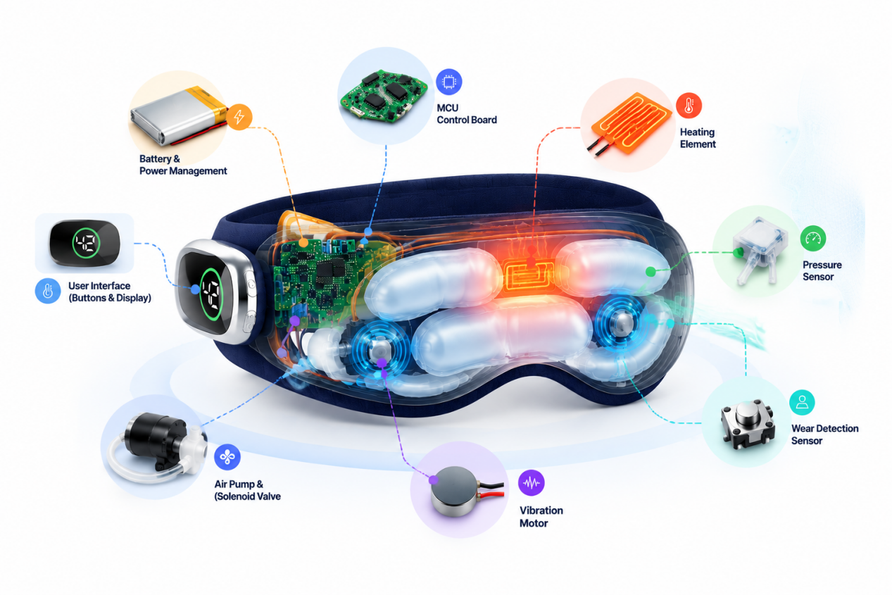
The sensor module acts as the device’s sensory system. It typically includes temperature sensors, air pressure sensors, and wear-detection sensors.
A temperature sensor near the heating area monitors surface temperature and provides feedback for temperature control. A pressure sensor in the air circuit measures airbag pressure, helping the controller regulate the pressure applied around the eyes. Wear-detection sensors identify whether the device is being worn, helping prevent unintended heating or inflation when it is not in use.
Together, these sensors continuously collect operating and wear-status data and send it to the MCU. The data provides the input needed for closed-loop temperature and air pressure control.
2.3 Actuator and Driver Module
The actuator module converts control signals into physical actions. Its main components include the air pump, vibration motors, and heating elements.
When the MCU sends a command, the driver circuits coordinate the miniature air pump and solenoid valves to inflate and deflate the airbags in cycles, creating a massage effect that mimics gentle squeezing and pressing. Vibration motors can be driven using pulse-width modulation (PWM), with duty-cycle adjustments used to control vibration intensity. The heating elements provide controlled warmth around the eye area.
Together, these driver circuits and actuators produce the massage functions users experience.
2.4 User Interface, Power Management, and Communication
The user interface typically includes physical buttons and LED indicators. Some higher-end models also feature a compact OLED display, allowing users to switch massage modes and check device status.
The power management module handles lithium-ion battery charging and discharging while supplying stable power to the device’s hardware components. It may also include basic power protection features.
For wireless connectivity, many smart eye massagers use Bluetooth Low Energy (BLE) to connect the MCU to a mobile app. This connection can allow users to customize massage settings and synchronize device usage records, depending on the product’s software and feature set.
3. Embedded Firmware and Low-Level Software Logic

3.1 Software Architecture: Bare-Metal vs. Lightweight RTOS
When developing firmware for a smart eye massager, you have two main options: bare-metal programming or a lightweight real-time operating system (RTOS).
Bare-metal programming is simpler and uses fewer system resources, making it suitable for basic eye massagers with limited functions and fewer tasks. A lightweight RTOS supports multitasking and is better suited to advanced models that need to handle sensor data acquisition, motor control, and Bluetooth communication at the same time.
Your choice should depend on your product positioning, functional requirements, and available hardware resources.
3.2 Low-Level Drivers and Task Scheduling
Low-level drivers act as the interface between the MCU and the hardware. They include sensor drivers, solenoid valve drivers, motor drivers, and Bluetooth drivers.
During operation, the firmware schedules different tasks to run at the appropriate times. These tasks include reading sensor data at regular intervals, sending control signals, monitoring button inputs, and maintaining Bluetooth connections.
You need to assign task priorities carefully to prevent control delays, sluggish responses, or interruptions during operation.
3.3 Programming Massage Modes
The kneading, compression, and automatic combination modes you select on an eye massager are essentially predefined timing sequences implemented in the firmware.
Each mode uses a different set of parameters, such as airbag inflation and deflation intervals, motor activation timing, and target heating temperature. When you switch modes, the firmware loads the corresponding parameter set and generates a sequence of control signals to deliver the intended massage pattern.
4. Core Closed-Loop Control Techniques
Smart eye massagers rely on different control methods to manage heating, airbag compression, and vibration. Each function uses specific components and control logic to deliver the intended output:
| Control Function | Key Components | Control Method | Primary Purpose |
| Heating | Temperature sensor, heating element, MCU | PID closed-loop control | Maintain a stable target temperature |
| Airbag Compression | Pressure sensor, air pump, solenoid valve, MCU | Pressure feedback control | Regulate airbag pressure and inflation cycles |
| Vibration | Vibration motor, driver circuit, MCU | PWM control | Adjust motor drive level and vibration intensity |
| Multi-Mode Coordination | MCU, firmware, multiple actuators | Task scheduling and timing logic | Coordinate heating, compression, and vibration |
4.1 PID Temperature Control for Heating
Heating is a basic function of many eye massagers. To maintain a stable target temperature, you can use a proportional-integral-derivative (PID) closed-loop control algorithm.
The process is straightforward: a temperature sensor continuously measures the actual temperature, and the MCU compares it with the target temperature. The PID algorithm then adjusts the heating element’s output based on the difference between the two values.
This approach helps reduce temperature fluctuations and maintain more consistent warmth around the eyes.
4.2 Closed-Loop Air Pressure Control
Airbag compression relies on closed-loop pressure control. A pressure sensor continuously measures the pressure inside the airbag and sends feedback to the MCU.
When the pressure falls below the target level, the system activates the air pump. Once the pressure reaches the specified threshold, the controller stops inflation or opens a solenoid valve to release air.
This feedback mechanism helps maintain more consistent air pressure and reduces variations in compression across different wearing conditions.
4.3 Vibration Motor Speed Control and Multi-Mode Coordination
Pulse-width modulation (PWM) allows you to control vibration motor speed and intensity. By adjusting the PWM duty cycle, the controller can change the motor’s drive level and, depending on the motor and driver design, its vibration intensity.
Multi-mode coordination involves scheduling the airbags, vibration motors, and heating elements to work together. When you select an automatic combination mode, the firmware coordinates these components according to predefined timing and control parameters.
5. Safety, Reliability, and EMC Design
5.1 Hardware Protection: Overcurrent, Overtemperature, and Short-Circuit Protection
Hardware protection circuits provide the first line of defense against electrical and thermal faults.
During hardware design, you need to incorporate appropriate protection mechanisms to monitor current and heating element temperature. If an overcurrent, abnormal temperature, or short circuit is detected, the protection circuitry can shut down the affected output to help prevent hardware damage and reduce potential safety risks.
The specific protection strategy depends on the circuit design and the requirements of the finished product.
5.2 Software Protection: Watchdogs, Fault Detection, and Automatic Shutdown
Hardware protection should be complemented by software-based safety mechanisms.
A watchdog monitors firmware execution. If the program becomes unresponsive, the watchdog can trigger a system reset. The firmware can also monitor sensor readings and actuator status to detect abnormal operating conditions.
When a fault is detected, the system can initiate a safe shutdown sequence, stopping heating, airbag inflation, and vibration as appropriate to the fault.
These mechanisms help improve system reliability and reduce the risk of continued operation under abnormal conditions.
5.3 PCB Layout and EMC Optimization for Wearable Devices
Smart eye massagers are compact wearable electronic devices. Their PCBs may need to accommodate Bluetooth circuitry, motors, sensors, and heating controls in a limited space, creating potential electromagnetic interference (EMI) challenges.
During PCB layout, you should carefully separate sensitive analog signals, power circuits, and communication lines. Proper grounding, routing, component placement, and power management also help reduce interference.
Effective electromagnetic compatibility (EMC) design helps prevent internal components from disrupting one another, improves operating stability, and supports compliance with applicable EMC requirements.
6. Technical Challenges and Future Developments in Smart Eye Massagers
6.1 Limitations of Current Embedded Designs
Current embedded designs for eye massagers still face several challenges. Sensor readings may vary with wearing fit and skin contact. Limited battery capacity can also make power consumption a concern when multiple functions operate together.
In some cost-sensitive designs, lower-precision sensors may lead to variations in temperature or pressure control.
When developing your product, you need to consider sensor consistency, power optimization, and control accuracy together rather than treating them as separate issues.
6.2 Adaptive Massage and Embedded AI
Embedded AI may offer new possibilities for future eye massagers. By collecting data on wearing conditions and user interactions, a device could potentially adjust pressure, temperature, or massage timing based on predefined rules or supported adaptive algorithms.
Instead of relying entirely on a fixed set of massage programs, future designs may offer more personalized operating patterns.
However, automatically detecting eye fatigue or determining an individual’s ideal massage settings requires appropriate sensing capabilities, validated algorithms, and supporting evidence. These functions should be treated as development possibilities rather than established capabilities of every smart eye massager.
Author Bio
I’m Viva, and my work focuses on massage product development and manufacturing, covering devices for different parts of the body. I’m particularly interested in the embedded technology behind these products, from MCU control and sensor feedback to temperature regulation, motor control, and system reliability.
I share practical insights into massage product design, engineering, and manufacturing, exploring how these elements shape product performance and user experience. You can connect with me on LinkedIn for more industry insights.


