
How Embedded Systems Control Modern Smart Ceiling Fan Lights
Modern homes demand more flexible control than traditional mechanical, fixed-function electrical systems can provide.
As integrated devices for both airflow and lighting, smart ceiling fan lights are evolving from passive actuators into intelligent terminals capable of sensing conditions, making closed-loop decisions, and adjusting operation automatically.
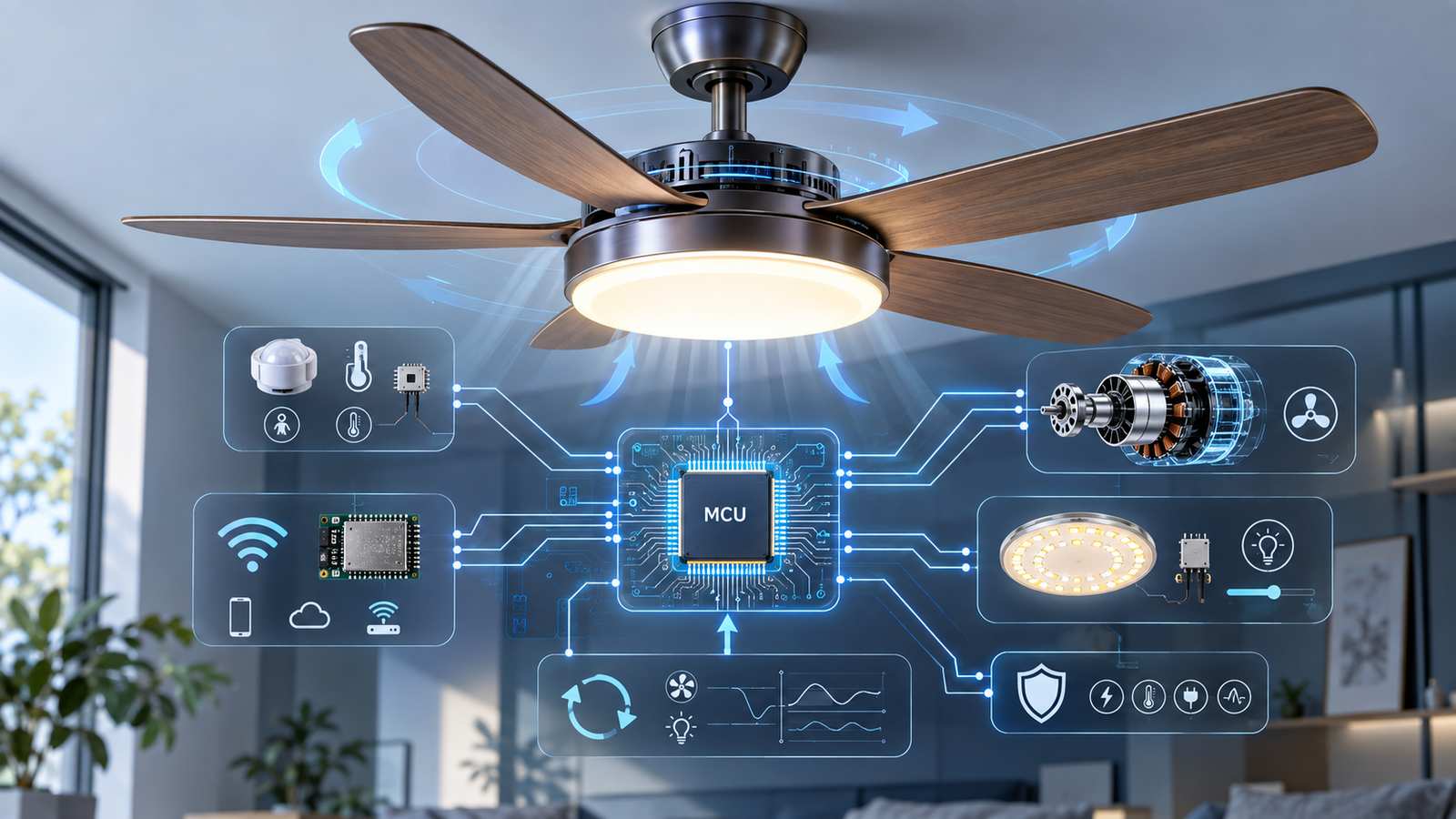
Unlike traditional open-loop circuits, modern smart ceiling fan lights use an MCU as the control core, integrating sensor input, real-time task scheduling, BLDC motor control, LED dimming, and safety protection into a coordinated embedded system.
Most product descriptions focus on visible smart features but rarely explain the control architecture behind them. Based on long-term engineering development, this article breaks down how embedded systems manage and control modern smart ceiling fan lights.
1. Embedded System Architecture for Smart Ceiling Fan Lights
1.1 Layered Architecture for Motor and Lighting Control
Smart ceiling fan lights use a 3-layer embedded architecture to separate hardware control from application logic.
The MCU core handles signal acquisition, algorithm processing, and task scheduling, serving as the system’s control center.
The firmware driver layer manages register configuration and low-level peripheral drivers, providing standardized hardware interfaces while abstracting device differences.
The application layer handles fan speed control, lighting adjustment, sensor integration, and communication.
This layered design supports modular hardware and software upgrades, allowing hardware changes without affecting upper-level application logic while improving system stability and portability.
1.2 Real-Time Control for Speed and Lighting
Traditional ceiling fan lights use fixed, open-loop controls with no environmental sensing or status feedback.
Embedded systems use an MCU for real-time closed-loop control, adjusting fan speed and lighting based on motor and sensor data.
This adds status monitoring, fault detection, and autonomous decision-making, turning the fan light from a simple actuator into an intelligent, self-adjusting device.
1.3 Coordinated Control of Airflow, Lighting, Sensors, and Connectivity
Smart ceiling fan light embedded systems handle concurrent tasks such as motor control, lighting, sensor sampling, and communication.
A priority-based scheduler gives motor control the highest priority, while sensor data is collected periodically and lighting updates and remote commands run at lower levels.
Dynamic resource allocation and task isolation prevent blocking and contention, keeping airflow, lighting, sensing, and communication stable and synchronized.
2. MCU Embedded Hardware & Signal Processing
2.1 MCU I/O Design for Motors, LEDs, and Sensors
The MCU acts as the core controller of the embedded system, coordinating all fan-light peripherals through careful hardware resource allocation. On-chip timers, ADCs, GPIOs, and serial interfaces are assigned by function: high-precision timers handle BLDC motor PWM control and smooth LED dimming, ADC channels sample electrical and sensor signals, serial ports connect wireless modules, and GPIOs support buttons and status indicators.
A priority-based scheduler gives motor control first access to critical resources, while lower-speed monitoring tasks share resources through time slicing. This prevents timing conflicts and resource contention, allowing multiple peripherals to run reliably in parallel within the MCU’s limited processing capacity.

2.2 Sensor Data for Speed and Environment
Complex electromagnetic environments can introduce high-frequency noise and transient interference into sensor data, causing false device responses.
The MCU continuously samples occupancy, temperature, humidity, and ambient light signals, then applies digital filtering to remove abnormal spikes and smooth the data.
Threshold-based logic converts the filtered signals into reliable environmental and occupancy states.
Embedded signal processing improves sensing accuracy and provides reliable data for adaptive fan speed control, smart lighting, and energy-saving standby.
2.3 Wireless Speed and Lighting Control
The wireless communication module extends the embedded system’s network connectivity and exchanges data with the MCU through a serial interface.
The firmware handles module initialization, network setup, data-frame validation, and retransmission, creating a communication link between the device, mobile app, and cloud.
The MCU processes remote commands in real time, updates motor and lighting settings, and uploads operating status and sensor data.
If the network becomes unstable or disconnects, the embedded system can continue running local preset controls and automatically resynchronize data after reconnection, balancing remote flexibility with reliable local operation.
3. Embedded Firmware and Real-Time Scheduling
3.1 Motor and Lighting Firmware Initialization
Firmware initialization is the first critical step after power-up and directly affects hardware stability and timing accuracy. The firmware configures the system clock, interrupts, timers, ADC, and serial interfaces to establish a standardized hardware operating mode. It then sets PWM frequency, sampling intervals, and interrupt priorities to meet the specific requirements of BLDC motor control, LED dimming, and sensor acquisition.
3.2 Real-Time Motor, Lighting, and Sensor Scheduling
Smart ceiling fan lights run multiple modules at the same time, so a single-loop architecture can cause task blocking and control delays.
The embedded firmware therefore uses a priority-based time-sliced multitasking scheduler, assigning task priorities and time slots based on real-time requirements. The scheduling rules are shown below:
| Task | Priority | Schedule | Core Function |
|---|---|---|---|
| BLDC Motor Control | Highest | Millisecond cycle | Adjusts motor speed and commutation in real time for smooth operation |
| LED Lighting Control | Medium-High | Short-cycle polling | Updates brightness and color temperature for smooth, flicker-free dimming |
| Sensor Sampling | Medium | Periodic sampling | Collects environmental and occupancy data for adaptive control |
| Communication Processing | Lowest | Asynchronous | Processes local and remote commands without occupying critical resources |
This scheduling approach prioritizes real-time tasks and handles lower-priority tasks asynchronously, reducing conflicts and system delays. It helps smart ceiling fan lights maintain stable, reliable operation throughout the day.
3.3 Setting Storage and OTA Update
The embedded firmware stores user settings in on-chip Flash memory, allowing parameters such as fan speed, lighting settings, and smart-scene thresholds to be restored after a power cycle.
A lightweight OTA mechanism also enables remote firmware updates through the wireless module.
The system verifies update packages, writes the new firmware in the background, and supports backup and rollback if an update fails or power is interrupted. This allows remote feature updates, algorithm improvements, and security fixes without opening the ceiling fan light.
4. Embedded Control of BLDC Motor and LED

4.1 PWM Speed and Direction for BLDC Motors
BLDC motors use electronic commutation, so speed and phase control depend on precise embedded timing.
The MCU generates high-frequency PWM signals and adjusts duty cycle for smooth, stepless speed control beyond fixed fan-speed settings.
Firmware monitors back-EMF signals to determine rotor position and switches drive phases according to the commutation logic.
A closed-loop control system also tracks motor current and speed, then adjusts PWM output to compensate for load changes. This keeps the BLDC motor smooth, quiet, and efficient.
4.2 Airflow and Seasonal Motor Reversal
Constant-speed airflow can feel harsh and uncomfortable. Embedded firmware uses lightweight in-house algorithms to simulate natural airflow and control seasonal fan direction without extra hardware.
By continuously varying PWM output and duration, the system creates changing airflow patterns instead of constant direct wind.
In summer, forward rotation improves air circulation and cooling; in winter, reverse rotation helps push warm ceiling air downward and balance room temperature.
The MCU executes these controls in real time for fast, smooth adjustment to changing indoor conditions.
4.3 LED Brightness and Color Temperature
Smart ceiling fan lights use a constant-current LED driver to maintain stable output and reduce flicker caused by voltage fluctuations. The embedded system then provides precise control of both brightness and color temperature.
The MCU outputs two independent PWM signals for cool-white and warm-white LEDs. Adjusting their duty-cycle ratio enables smooth color-temperature changes, while changing the overall duty cycle controls brightness.
Ambient light sensors provide data for adaptive lighting control. The firmware can increase brightness during the day and reduce brightness with warmer light at night. Smooth-transition algorithms prevent sudden changes, improving visual comfort while supporting stable LED operation.
5. Fault Detection & Safety Protection
5.1 Motor Overcurrent, Stall, and Overtemperature Detection
As the core in a ceiling fan light, the BLDC motor can be affected by blockage, sudden load changes, and poor heat dissipation. The embedded system uses the MCU’s high-speed ADC to monitor bus current, driver temperature, and operating status in real time.
Stall faults are detected through sudden current spikes and loss of speed feedback. Overcurrent is identified when current exceeds preset thresholds, while overheating is monitored through continuous temperature tracking and rising thermal trends.
These software-based diagnostics help prevent motor damage and driver failure without adding extra external protection circuits.
5.2 Motor and Lighting Circuits
To balance safety and continuous operation, the system uses a layered fault-tolerance strategy that combines hardware and software protection.
At the hardware level, built-in current limiting and thermal shutdown provide the fastest first line of protection.
At the software level, embedded firmware classifies faults and applies different responses based on severity.
Minor faults trigger parameter adjustment and local warnings, moderate faults reduce power and limit current, while severe faults immediately disable PWM output and lock the motor driver.
This graded protection approach helps maintain operation when possible while preventing unsafe conditions and hardware damage.
5.3 Fault Logging, Automatic Reset, and Recovery
For common embedded-system faults such as electromagnetic interference, firmware crashes, and transient voltage fluctuations, the firmware uses a watchdog reset mechanism to automatically restart the system when tasks freeze or software fails.
The system also stores fault type, timing, and operating parameters in non-volatile memory for maintenance and firmware improvement.
Temporary faults trigger automatic recovery and restart once conditions return to normal, while permanent hardware faults keep the system locked in protection mode until manual intervention.
This creates a closed-loop safety process of monitoring, protection, recording, and self-recovery.
6. Embedded System Optimization and Technology Evolution
6.1 Real-Time Control Accuracy Optimization
Control errors in smart ceiling fan light embedded systems mainly come from task-scheduling jitter, sampling delays, and inefficient algorithms. Firmware timing, interrupt priorities, ADC sampling, and PWM control can be optimized to reduce latency and improve high-priority motor and lighting control.
6.2 Low-Power and Reliable Operation
Smart ceiling fan lights often remain in standby for long periods and switch on and off frequently. The embedded system reduces power consumption by disabling unnecessary peripheral clocks and high-frequency sampling during standby while keeping essential sensing and wake-up functions active.
The wireless system also optimizes advertising intervals and connection parameters to reduce power use while maintaining reliable connectivity. Improved interference resistance and fault handling further support stable operation in complex home environments.
6.3 From Standalone Control to Ecosystem
Traditional ceiling fan lights mainly operate as standalone devices with limited connectivity and scalability. Embedded systems are now evolving them into connected nodes within whole-home smart ecosystems.
Standard communication protocols also enable ceiling fan lights to interact with lighting, security, and climate-control devices, supporting coordinated scenes and more adaptive home environments.
Author Bio:
I’m Arrebol Su, focusing on smart ceiling fan lights, embedded control systems, and intelligent product design. Through my work with NEBOLA, I explore how MCUs, motor control, LED dimming, sensors, and wireless modules work together to improve the performance and reliability of modern ceiling fan lights.
I regularly share insights on embedded systems, product development, and smart fan-light technologies through my LinkedIn updates. I’m always happy to discuss new ideas and practical engineering solutions.


