
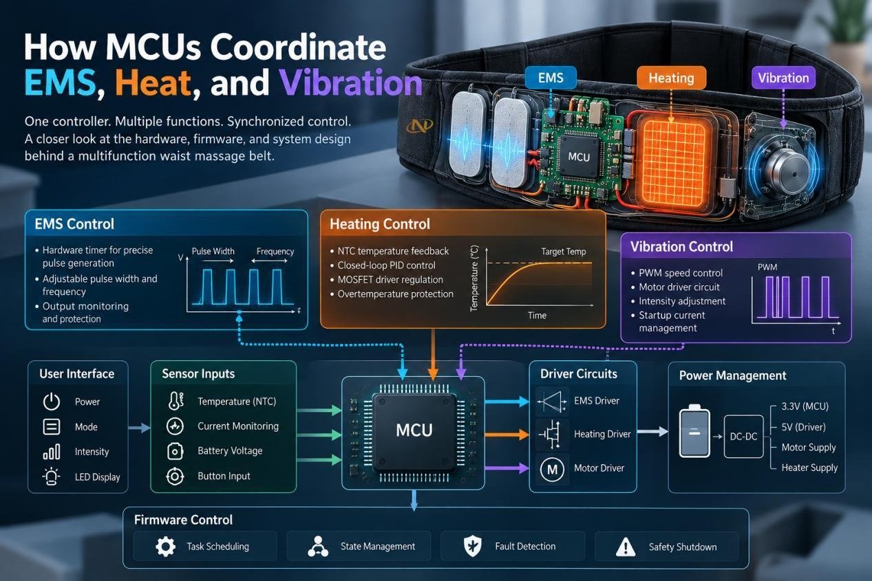
How MCUs Coordinate EMS, Heat, and Vibration
An MCU coordinates EMS, heating, and vibration by managing their control signals, timing, operating states, and sensor feedback through a centralized control architecture. Rather than treating each function as an independent circuit, the MCU determines when each function should operate, adjusts its output according to user settings and sensor inputs, and manages their interaction when multiple functions run at the same time.
Take a multifunction waist massage belt as an example. A user may activate EMS while maintaining a selected heating level and then add vibration. At this point, the MCU needs to maintain the EMS pulse sequence, monitor temperature feedback, send the appropriate command to the vibration driver, and respond to changes in system status. Meanwhile, the PCB power architecture must supply these loads without allowing voltage fluctuations or electrical noise to disrupt control signals or output performance.
The following I will examine how the MCU handles each function individually, how it coordinates them during simultaneous operation, and how the PCB architecture supports reliable system-level control.
1. Why Do Multifunction Massagers Need MCU Control?
Independent Functions vs. Coordinated Control
EMS needs repeatable pulse timing; heating needs temperature feedback; vibration needs a motor drive. Running all three independently risks inconsistent operating states and unmanaged peak loads. Centralized control defines which functions may run together and how they respond to user input.
Wearable Waist Massagers as an Application
Starbright’s custom waist massager range includes EMS/TENS-and-heating configurations and separate heating-and-vibration designs. These are examples of different electronic subsystems, not evidence that one existing model contains all three. A combined design would require integrated power and safety verification.
Timing, Power, and Safety Requirements
The design must preserve time-critical outputs, supply peak current, and disable unsafe operation. Those requirements determine MCU peripherals, driver selection, PCB routing, and firmware states.
2. How Is the MCU Control System Designed?
MCU and Peripheral Architecture
A suitable MCU provides hardware timers for EMS timing, PWM channels for motor or heater control, ADC inputs for temperature and electrical feedback, and GPIO for buttons and indicators. Hardware peripherals reduce dependence on software delays. IoTbyHVM’s microcontroller development board overview introduces these interfaces.
EMS, Heating, and Motor Driver Circuits
The MCU sends control signals to separate output stages. An EMS driver generates the specified electrode waveform; a MOSFET switches a resistive heater; a motor driver handles vibration current and switching transients. Driver ratings must match the actual loads, not merely the MCU’s logic voltage.
Sensor Inputs and Control Interfaces
Temperature sensors, supply monitoring, and driver fault signals inform firmware decisions. The user interface should clearly distinguish intensity, heat, vibration, and session time. Power-up and mode changes must begin from defined output states.
3. How Does the MCU Control EMS Output?
Timer-Based Pulse Generation
Hardware timers schedule pulse edges or trigger the EMS output stage at defined intervals. This avoids jitter caused by button scanning or temperature calculations. Accurate timing still requires verification at the electrodes because the driver and connected load affect the delivered waveform.
Pulse Frequency, Width, and Intensity
Firmware selects approved pulse profiles covering frequency, width, amplitude, and waveform shape. Intensity commands should map to a validated electrical output range; changing a timer value alone does not establish delivered current. Multichannel designs also require checks for channel interaction.
Output Monitoring and Protection
Depending on the circuit, voltage feedback, current sensing, or driver diagnostics can identify abnormal output behavior. The output stage needs a reliable disable path during faults or MCU resets. Verification should use representative loads and the intended electrode configuration.

4. How Does the MCU Regulate Heating?
Temperature Sensing and Feedback
An NTC thermistor changes resistance with temperature. A divider and ADC let firmware estimate temperature from a calibrated curve. Sensor placement is critical: a reading near the controller may miss a hotter skin-contact area.
MOSFET-Based Heating Control
The MCU can regulate a resistive heater using hysteresis control or an appropriate PWM strategy. Duty cycle influences average electrical power, but surface temperature also depends on insulation, belt fit, and ambient conditions. Test the assembled wearable, not just the heating element.
Overtemperature Detection and Protection
Firmware should detect implausible sensor readings and stop heating. Independent thermal protection is also important because a stuck switching device or software fault can defeat normal feedback control. Protection thresholds must follow the product’s risk assessment and applicable requirements.
5. How Does the MCU Control Vibration Motors?
PWM and Motor Driver Design
For an eccentric rotating mass (ERM) motor, PWM changes average drive power and generally affects vibration intensity. A transistor or dedicated driver supplies motor current, with suitable suppression for inductive transients. Linear resonant actuators need a different, resonance-aware drive approach.
Speed Control and Startup Current
Motor startup may draw substantially more current than steady operation. This matters when EMS and heating share the battery. Open-loop PWM does not measure motor speed; use calibration or feedback if the design requires accurate speed regulation.
Motor Noise and Electrical Protection
Switching and commutation can disturb analog measurements or EMS circuitry. Check supply ripple and output waveforms while the motor runs. Detailed filtering and return-current routing belong in the PCB design, not in firmware alone.
6. How Are Multiple Functions Scheduled?
Timers, Interrupts, and Task Priorities
EMS pulse timing should remain in hardware timers or tightly bounded interrupt routines. Temperature sampling and button scanning can run as periodic tasks; motor PWM can operate independently in a timer peripheral. Safety faults take priority over routine interface updates. Avoid lengthy calculations inside time-critical interrupts. Temperature ADC sampling can also be scheduled away from noisy motor-switching edges when measurements show interference; that decision should be based on actual board behavior.
Mode Switching and State Machines
A finite-state machine defines standby, active, transition, fault, and shutdown behavior. When the user changes EMS intensity, firmware can update the driver through an approved transition rather than modifying outputs unpredictably. State rules also prevent prohibited function combinations and unexpected restart after power loss.
Coordinating Simultaneous Operations
Engineering scenario: EMS and heating are active when vibration starts. Motor inrush pulls down the shared supply, potentially disturbing the EMS driver or triggering an MCU brownout. Firmware can sequence startup, check supply voltage, and restrict combinations when necessary. The power system must still tolerate the specified peak load; software cannot repair an undersized regulator.
A useful validation sequence records the EMS waveform and supply rail before, during, and after motor startup. If the waveform shifts, investigate supply impedance, driver isolation, and ground return paths before changing task priorities. This is an illustrative design scenario, not a reported product defect.
7. How Are Power and PCB Design Optimized?
Battery Power and Load Distribution
Use watt-hours to estimate energy. For an illustrative 3.7 V, 2,500 mAh battery, nominal energy is 9.25 Wh. At an average 6 W load, ideal runtime is about 1.54 hours before conversion losses and discharge limits. Peak current, especially motor startup plus heating, requires separate analysis. These are not Starbright product specifications.
Grounding and EMI Reduction
Keep high-current switching loops short, place decoupling near drivers, and route sensitive ADC and EMS signals away from noisy nodes. Ground strategy should follow actual return-current paths; arbitrarily splitting the ground plane may make interference worse. Evaluate conducted noise under combined operation.
PCB Layout and Thermal Management
Separate heat-generating switches from temperature-sensing circuitry where practical. Account for flexible cables, connector retention, and strain relief in a moving belt. Thermal measurements should include realistic fastening pressure and operating modes.
8. How Does Firmware Handle System Faults?
Sensor and Output Fault Detection
Define valid ranges for sensor readings, supply voltage, and driver feedback. An open or shorted thermistor may produce an implausible ADC value; the controller should disable heating rather than continue using stale temperature data.
Watchdog Timers and Safe Shutdown
A watchdog can recover from some firmware hangs, but it cannot replace hardware protection. Driver enable signals should default to a safe state during reset and startup. Hazardous outputs must not rely solely on a software instruction to switch off.
Fault Recovery and User Feedback
In a hypothetical thermistor-disconnection test, heating shuts down and the interface reports a fault. Reconnection should not silently restart the heater unless explicitly permitted by validated safety logic. Record the fault response and recovery conditions.
9. How Is the Integrated System Tested?
EMS Timing and Output Verification
Measure pulse timing and delivered waveforms with suitable instruments and representative loads. Repeat during mode changes, low battery, and vibration startup. Compare results against the approved electrical specification.
Heating and Motor Performance Testing
Record skin-contact temperatures, sensor response, motor startup current, and supply ripple under defined conditions. Include realistic belt fit and ambient temperature in the test plan.
Combined-Load and Reliability Testing
Individual-function tests can miss cross-system failures. The final validation matrix should cover simultaneous operation and abnormal states:
| Test condition | Critical measurements | What it reveals |
|---|---|---|
| EMS + vibration | Pulse waveform, supply ripple | Motor interference |
| Heating + vibration | Temperature, startup current | Load interaction |
| All functions active | Peak current, MCU stability, contact temperature | System margin |
| Sensor disconnected | Heater shutdown, fault indication | Protection response |
| Low battery / repeated cycles | Reset behavior, output drift | Reliability |
Author Bio:
I’m Viva. I work with massage products, from waist and leg massagers to full-body massage devices.I pay attention not only to comfort and user experience, but also to the embedded systems behind these products — including MCU control, EMS pulse timing, temperature regulation, vibration motor control, and system reliability.
I look at massage products from both the product and manufacturing sides, and I share practical insights and industry observations on my LinkedIn. If you like talking shop about what makes a massage product tick, we’ll probably get along.


