
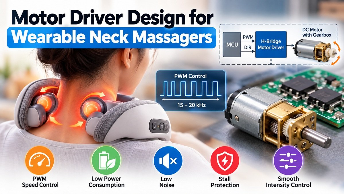
Motor Driver Design for Wearable Neck Massagers
Wearable neck massagers use DC motors and reduction gears to generate kneading and massage motions. Motor drive design directly affects massage intensity, noise, battery life, and safety. Key engineering challenges include PWM speed control, driver circuit selection, startup current limiting, and overload protection. Neck and shoulder massagers also face fluctuating loads and motor stalls caused by body pressure, requiring reliable drive control to manage battery limitations and changing loads.
1. Overview of Motor Drive Systems in Wearable Neck Massagers
1.1 Motor Drive Requirements
Wearable neck and shoulder massagers use multiple massage heads powered by DC motors and worm-gear reduction mechanisms. These systems simulate finger pressure, kneading, and pushing motions to target muscles such as the trapezius and splenius cervicis. Many designs offer adjustable intensity, bidirectional motor rotation, and temperature-controlled heating. Some can also be used on the lower back and legs.
These devices face several engineering challenges:
- Low power consumption: Battery-powered operation requires an efficient drive system.
- Low noise: Motors must operate quietly during use.
- Stall protection: Leaning against the massage heads can overload or stall the motor.
- Smooth intensity control: Speed changes should not cause sudden pressure, vibration, or mechanical shocks.
1.2 System Architecture and Design Constraints
A typical motor drive system consists of an MCU, PWM controller, H-bridge driver, DC kneading motor, current-sensing circuit, and protection logic.
Motor torque passes through a reduction gearbox to drive multiple silicone massage heads in alternating kneading motions.
The design must balance four priorities: battery life, output torque, operating noise, and safety. Battery capacity limits continuous power consumption, while the worm-gear mechanism introduces additional load and potential stall conditions. Managing current spikes during these conditions is a key design challenge.
2. PWM Speed Control and Parameter Selection
2.1 How PWM Speed Control Works
Pulse-width modulation (PWM) controls DC motor speed and output by adjusting the duty cycle of a fixed-frequency signal.
A higher duty cycle increases the motor’s effective average voltage, generally allowing greater speed and torque under load. A lower duty cycle reduces output.
Unlike basic on/off control, PWM allows gradual speed adjustments and smoother transitions between massage intensity levels.
2.2 Selecting PWM Parameters
PWM settings must match the motor’s electrical and mechanical characteristics.
A low switching frequency can cause audible noise and uneven motion. An excessively high frequency increases switching losses, heat generation, and battery consumption.
| Parameter | Suggested Setting | Engineering Consideration |
| PWM frequency | 15–20 kHz | Reduce audible motor noise while managing switching losses |
| Duty cycle range | 10–100% | Maintain adequate starting torque and avoid stalling at low duty cycles |
| PWM adjustment | Gradual duty cycle ramping | Prevent sudden changes in massage intensity |
2.3 Benefits of PWM Control
PWM offers three main advantages for wearable kneading massagers:
- Smooth intensity adjustment: Gradual duty cycle changes reduce abrupt movements.
- Higher efficiency: Compared with linear voltage regulation, PWM generally reduces power losses and supports longer battery life.
- Flexible motor control: MCU-controlled PWM and direction signals enable alternating forward and reverse kneading patterns.
3. Motor Driver Circuit Design
3.1 Selecting the Drive Topology
An H-bridge is a common solution for bidirectional DC motor control. By reversing the voltage polarity across the motor, it enables forward rotation, reverse rotation, and stopping.
Power MOSFETs inside the H-bridge switch motor current, while the MCU provides PWM and direction-control signals.
Compared with a discrete MOSFET design, an integrated H-bridge driver can simplify PCB layout, reduce component count, and save space inside a compact neck massager.
3.2 MCU and Motor Interfaces
The MCU sends PWM and direction signals to the motor driver through suitable interface circuitry.
Depending on the design, level shifting, input protection, or electrical isolation may be needed to protect the controller from electrical noise and voltage disturbances.
The motor drive circuit also requires appropriate freewheeling paths to handle inductive current during switching and shutdown. These may be provided by the H-bridge’s integrated protection structures or external components.
Although a worm-gear mechanism may resist back-driving, motor reversal can still produce current surges and voltage transients. Proper switching control and circuit protection remain essential.
3.3 Supporting Circuits
The motor drive system also includes:
- Voltage regulation: Supplies stable operating voltages to the MCU and driver circuitry.
- Current sensing: Measures motor current for overload and stall detection.
- Filtering and EMI control: Reduces switching noise that could interfere with temperature sensing and button inputs.
These circuits help maintain stable operation under changing mechanical loads.
4. Startup Current Control
4.1 Why Startup Current Spikes Occur
When a DC motor starts from rest, its back electromotive force (back EMF) is nearly zero. This can produce an inrush current several times higher than its normal operating current.
A worm-gear mechanism and loaded massage heads may increase starting resistance.
Large startup current spikes can cause battery voltage drops, MCU resets, or unintended activation of battery protection circuits. Repeated surges also place additional stress on motor brushes and power MOSFETs.
4.2 Soft-Start Current Limiting
Soft-start control gradually increases PWM duty cycle instead of immediately applying the target output.
This allows motor torque to build more smoothly and helps reduce startup current spikes.
Current feedback provides additional protection. If measured current exceeds the startup threshold, the MCU can temporarily reduce the duty cycle. Once the motor begins rotating and back EMF develops, the controller gradually increases output to the selected intensity.
4.3 Impact on Product Performance
Without soft-start control, repeated current surges can:
- Increase stress on the battery and power electronics.
- Accelerate wear in the motor and driver components.
- Cause sudden torque changes and uncomfortable pressure from the massage heads.
A properly tuned startup sequence improves both electrical reliability and user comfort.
5. Motor Overload Protection
5.1 Common Overload Scenarios
Wearable neck massagers operate under variable external loads.
Leaning backward, pressing against the massage heads, or trapping clothing in the mechanism can sharply increase motor resistance.
If the motor stalls, current can rise rapidly while the motor stops rotating. Prolonged stall conditions may cause excessive heating and damage to the motor, driver, or surrounding materials.
5.2 Stall Detection Through Current Sensing
A current-sensing circuit continuously monitors motor current.
During normal kneading, current fluctuates within an expected operating range. When a massage head becomes jammed, motor speed drops and current rises.
The firmware can use two protection thresholds:
- Warning threshold: Reduce PWM duty cycle to limit torque and current.
- Stall threshold: Shut down the motor if excessive current persists.
Thresholds and detection delays must account for normal load variations to avoid false trips.
5.3 Protection and Reset Logic
When a stall is detected, the controller disables the motor driver and enters a fault state.
The motor should remain stopped until the user manually resets the device.
This prevents unexpected movement after the obstruction is removed. Manual reset allows the user to check that the massage heads are clear before operation resumes.
6. System Performance and Reliability Testing
6.1 Low-Power Optimization
In addition to efficient PWM control, firmware can reduce unnecessary power consumption through automatic shutdown timers.
Battery voltage compensation may also help maintain more consistent massage output as the battery discharges.
As battery voltage falls, the MCU can adjust PWM duty cycle within validated operating limits. This reduces noticeable changes in motor performance while avoiding excessive current demand.
6.2 EMC and Noise Reduction
PWM switching generates electromagnetic interference that may affect temperature measurements, button inputs, and other low-voltage signals.
Good PCB design separates high-current motor paths from sensitive control circuits. Proper decoupling capacitors also help reduce supply noise.
Mechanical and electrical noise can be reduced by selecting an appropriate PWM frequency and controlling the rate of current changes during startup and motor reversal.
These measures support quieter and more stable operation.
6.3 Durability Testing
Motor drive reliability should be verified through repeated operating cycles, including:
- Frequent motor starts and stops.
- Forward and reverse rotation.
- Repeated stall protection and manual resets.
- High- and low-temperature operation.
- Extended operation under representative mechanical loads.
Testing should confirm stable intensity control, consistent fault detection, and reliable protection over the product’s intended service life.
7. Engineering Challenges and Future Development
7.1 Common Troubleshooting Issues
Three problems frequently arise during prototype testing and pilot production.
1. Motor vibration or unstable intensity
Possible causes include unsuitable PWM frequency, insufficient power-supply decoupling, or unstable motor loading.
2. False stall detection
Current-sense resistor tolerance, signal noise, or poorly tuned filtering can cause normal kneading current fluctuations to trigger protection.
3. Abrupt intensity changes
Without gradual duty cycle adjustment, switching between intensity levels can cause sudden torque changes and mechanical shocks.
7.2 PCB Layout Considerations
Reliable motor control depends on careful PCB layout.
Keep high-current drive paths short to reduce parasitic inductance and switching noise.
Route current-sensing signals away from PWM power traces to minimize interference.
Separate sensitive MCU, button, and temperature-sensing circuits from motor power circuitry.
Use an appropriate grounding strategy to control noise and prevent unwanted current coupling.
7.3 Future Motor Drive Technologies
Future wearable kneading massagers may adopt more integrated motor drivers, sensorless load estimation, and adaptive control algorithms.
By estimating changes in mechanical load, the controller could adjust PWM output to maintain more consistent kneading intensity.
More compact drive electronics could also reduce PCB size, device weight, and overall power consumption.
For manufacturers developing wearable neck massagers, the goal is to combine responsive motor control, reliable protection, and efficient hardware in a compact, comfortable product.
Author Bio
I’m Viva, and my work focuses on massage product development and manufacturing, covering devices for different parts of the body. I’m particularly interested in the embedded technology behind these products, from MCU control and sensor feedback to temperature regulation, motor control, and system reliability.
I share practical insights into massage product design, engineering, and manufacturing, exploring how these elements shape product performance and user experience. You can connect with me on LinkedIn for more industry insights.


