
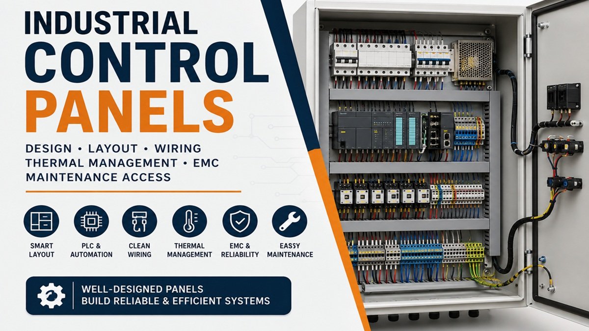
Industrial Control Panel Design: Layout, Wiring, Thermal Management and EMC
Industrial control panels are more than enclosures containing breakers, PLCs, relays, terminals and power supplies. The physical arrangement of those components directly affects electrical safety, commissioning time, electromagnetic compatibility (EMC), thermal performance and long-term maintainability.
A well-designed panel allows an engineer to understand the power path, control architecture and field connections quickly. A poorly planned panel may still operate during commissioning but become difficult to troubleshoot, expand or service later.
For machinery applications, IEC 60204-1 addresses electrical, electronic and programmable electronic equipment associated with machines and includes considerations such as protective bonding, overcurrent protection, EMC, control circuits and technical documentation.
Start the Cabinet Design With Functional Zones
Before mounting individual components, divide the cabinet into functional areas. A typical industrial automation panel may contain:
- Incoming power and main isolation
- Circuit protection and distribution
- Control power supplies
- PLC and remote I/O
- Safety components
- Contactors, motor starters and variable-frequency drives
- Industrial networking equipment
- Terminal blocks
- Field cable entry and termination
The objective is not simply to make the cabinet look symmetrical. Each component should have a logical relationship with the equipment it supplies, controls or communicates with.
A useful control panel layout should allow an engineer to trace the system from incoming supply through protection and control devices to the field terminals. When the physical arrangement follows the electrical drawings, troubleshooting becomes considerably easier because the technician can move through the same logical sequence in both the documentation and the cabinet.
Separate Power and Sensitive Control Circuits
One of the most important layout considerations is separation between high-energy circuits and sensitive electronics.
Contactors, motor starters, transformers and variable-frequency drives can produce electrical noise and transient disturbances. PLC CPUs, analogue input modules, communication interfaces and other sensitive electronics can be affected when wiring routes and component placement allow excessive coupling.
A practical cabinet design therefore separates wiring according to function. Depending on the machine and applicable standards, separate routing may be appropriate for:
- AC power conductors
- Motor and drive wiring
- 24 V DC control wiring
- Analogue instrumentation
- Safety circuits
- Ethernet and other communication cables
- Field I/O wiring
The exact separation method depends on the equipment manufacturer’s instructions, installation environment and applicable standards. EMC is a system-level design issue rather than something that can always be corrected by adding a filter after installation.
PLC Placement and Wiring
The PLC should be positioned so that its status indicators, connectors, module identification and wiring remain accessible.
Avoid installing a PLC where a bundle of field cables, relays or trunking permanently obscures diagnostic LEDs. During commissioning, technicians frequently need to inspect module status, replace an I/O module or trace a signal.
Terminal blocks should also follow a predictable numbering scheme that corresponds with the electrical drawings and cable schedules. IEC 60204-1 specifically addresses conductor and terminal identification and accessibility for operation and maintenance.
For analogue signals, shield handling deserves particular attention. The correct termination method depends on the instrument, PLC or signal conditioner and the overall EMC design. Shield conductors should not simply be connected according to habit; the intended grounding and bonding strategy should be defined in the engineering documentation.
Thermal Management Is Part of Electrical Design
A cabinet can be electrically correct and still have a thermal problem.
Power supplies, VFDs, transformers, contactors and other components dissipate heat. When several heat-producing devices are installed close together, the local temperature can become substantially higher than the surrounding room temperature.
Thermal design should therefore consider:
- Component power dissipation.
- Manufacturer-required clearances.
- Enclosure dimensions and material.
- Ambient temperature.
- Internal air circulation.
- Cooling or ventilation requirements.
- Heat generated by drives and power conversion equipment.
- Dust and environmental contamination.
Do not assume that leaving a small visual gap between components automatically provides adequate cooling. Manufacturer installation instructions and the enclosure’s calculated thermal performance should determine the required clearances.
Sensitive electronics can also benefit from being located away from concentrated heat sources. A PLC communication module operating beside a high-power drive may have a very different thermal environment from the same module installed in a cooler part of the enclosure.
Wiring Duct and Cable Routing
Wire duct should support the circuit architecture rather than simply provide a place to hide conductors.
Good routing makes it possible to:
- Follow a conductor from one device to another.
- Read wire markers without removing unrelated wiring.
- Remove trunking covers during maintenance.
- Add or replace conductors where expansion has been anticipated.
- Maintain appropriate separation between different circuit categories.
- Preserve the bend radius specified for cables.
Field wiring should normally terminate at clearly identified terminal blocks rather than creating an uncontrolled collection of direct connections to internal devices.
This creates a defined interface between the cabinet and the machine. It also simplifies factory testing because technicians can identify individual field circuits without repeatedly accessing sensitive PLC or relay terminals.
EMC: Think About the Complete Current Path
EMC problems in automation panels are often blamed on a single component when the actual problem is the overall installation.
Common contributors include:
- Long parallel runs between noisy and sensitive circuits
- Poor shield termination
- Inadequate bonding between metallic enclosure sections
- Incorrect cable selection
- Poor routing around VFDs
- Uncontrolled gaps or discontinuities in shielded enclosure structures
- Incorrect grounding or bonding practices
Sensitive PLC, computer and analogue equipment should be positioned with the electromagnetic environment in mind. Engineering references on EMC design specifically recommend considering the interference potential of equipment when deciding module placement and cable classes.
For drives and other high-frequency power electronics, follow the manufacturer’s EMC installation requirements rather than relying on generic grounding rules. Cable type, shield termination, bonding and routing can all affect the final result.
Maintenance Access Should Be Designed Before Assembly
A panel is not finished when every DIN rail is full.
Maintenance personnel need to inspect terminals, read labels, measure signals, replace components and perform fault diagnosis. Equipment that requires regular access should therefore be positioned where it can be reached without dismantling unrelated components.
IEC 60204-1 includes requirements concerning the accessibility and mounting of controlgear for operation and maintenance.
A useful design review should ask:
- Can the main isolation point be identified immediately?
- Can protective devices be inspected without moving wiring?
- Are PLC indicators visible?
- Can terminal screws or spring terminals be accessed?
- Can a failed power supply be replaced without dismantling half the cabinet?
- Can test equipment be connected safely?
- Are wire numbers still readable after installation?
- Is there enough room for future service work?
The answers often reveal layout problems before the cabinet reaches the production floor.
Leave Space for Future Changes
Industrial automation systems rarely remain completely unchanged throughout their operating life. Sensors are added, I/O points change, communication hardware is upgraded and obsolete components eventually require replacement.
A cabinet should therefore include practical provisions for expansion where the project requires it. This may include spare DIN-rail capacity, additional terminal positions, spare I/O capacity or reserved cable-routing space.
However, unused space should not be treated as an excuse for an undefined design. Spare capacity should be documented so that future engineers know what the reserved area is intended to support.
Design the Panel for Troubleshooting
A good control cabinet communicates its architecture visually.
An engineer opening the door should be able to identify:
Incoming supply → isolation → protection → power conversion → control system → switching/interface → field terminals
The exact arrangement will vary with the machine, but the principle remains useful: the physical cabinet should reinforce the electrical schematic rather than contradict it.
This becomes particularly valuable during faults. If a motor does not start, a technician may need to determine whether the problem originates in the incoming supply, branch protection, control voltage, PLC output, interposing relay, contactor, drive or field wiring.
A logical layout reduces the number of unrelated components that must be inspected during that process.
Final Engineering Review
Before manufacturing or installing an industrial control panel, review the design from four perspectives:
Electrical: Are protection, conductor sizing, isolation, bonding and short-circuit requirements correctly addressed?
Thermal: Are heat-producing components adequately spaced and is the enclosure’s thermal performance acceptable?
EMC: Are noisy and sensitive circuits routed appropriately, with shields and bonding implemented according to the design?
Maintenance: Can technicians identify, access, test and replace important components without unnecessary disassembly?
A technically strong control panel is therefore not simply a neat collection of components. Its layout, wiring, thermal design, EMC strategy and service access should all support the same engineering objective: a system that is safe to operate, predictable to commission, straightforward to troubleshoot and practical to maintain throughout its service life.


